Active production — no LTB clock ticking
The STTH10LCD06CFP: ROHS3 compliance is confirmed — no exempt substances, so the part clears EU and UKCA RoHS requirements without a waiver.
50 ns reverse recovery — where it fits in the switching band
A 50 ns trr places this diode in the fast-recovery class, suited for continuous-conduction-mode PFC boost stages, 50-100 kHz flyback converters, and output rectification in half-bridge topologies where the switching node sees 600 V max. The 600 V Vrrm gives 200 V of margin above a typical 400 VDC bus — enough for 230 VAC PFC with normal overshoot, but not enough for 800 V bus architectures or three-phase PFC without series stacking.
5 A per diode — the thermal ceiling in a full-pack
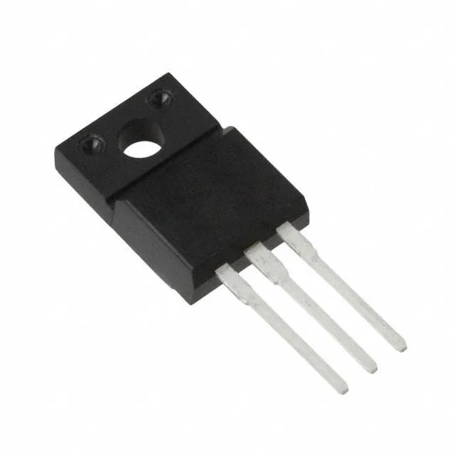
Each diode in the common-cathode pair is rated 5 A average rectified current. The TO-220FPAB full-pack isolates the tab electrically, saving an insulator pad, but the plastic body has a higher junction-to-case thermal resistance than a standard TO-220 — the real current ceiling at 175°C Tj is set by the heatsink interface, not the silicon. Reverse leakage is 1 µA at 600 V at 25°C, but doubles every 10°C junction rise. At 125°C the leakage is roughly 64 µA — still low for a 5 A diode, but the leakage power adds to the thermal budget in high-temperature environments.
Common-cathode pair — layout implications
The two diodes share a common cathode on the tab (pin 2 in TO-220FPAB), while the anodes are on pins 1 and 3. This configuration is standard for centre-tap secondary rectification and boost PFC where the cathodes tie to the output rail. Through-hole mounting in a TO-220-3 Full Pack means the leads are 0.025-inch thick and 0.55-inch pitch — a standard 0.1-inch grid layout works, but the tab hole in the heatsink must be drilled for the full-pack shoulder, not a standard TO-220.