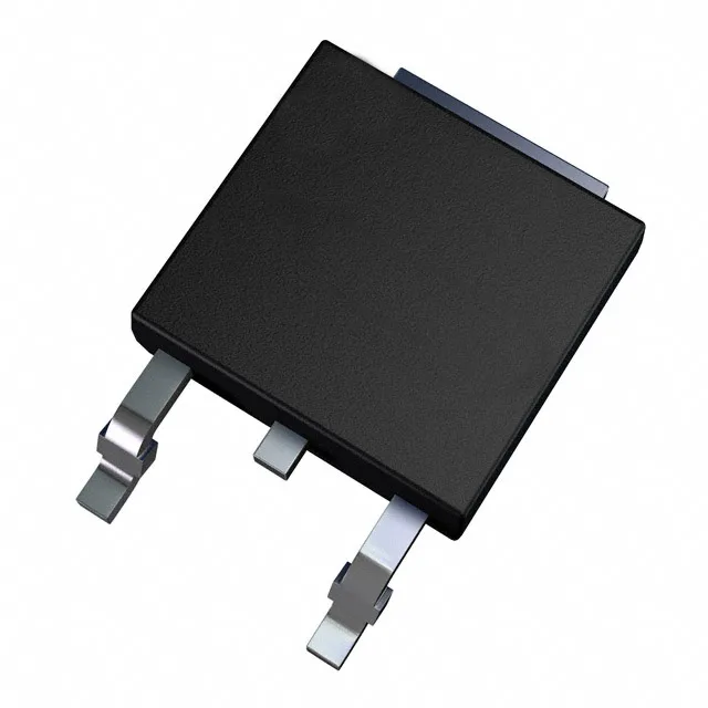
300 V, 10 A, 35 ns — the switching diode for PFC and flyback stages
Its 35 ns reverse recovery time (trr) places it squarely in the ultrafast class, suited for continuous-current-mode power-factor-correction (CCM PFC) boost stages, output rectification in flyback converters, and freewheeling diodes in hard-switched topologies where recovery charge drives the switching loss.
35 ns trr — what it costs the switching loop
A 35 ns trr at 10 A forward current means the diode sweeps out stored charge in roughly one switching cycle at a 100 kHz fundamental. In a CCM PFC boost stage, that recovery transient is the dominant turn-on loss in the MOSFET — the diode's snap-off characteristic must be clean enough not to ring the drain node. The 1.3 V forward drop at 10 A is a conduction-loss trade-off for the speed; a slower 60 ns part would drop less Vf but cost more in switching loss at higher frequencies.
175°C junction — thermal budget for the copper plane
The 175°C max junction temperature gives headroom above the 150°C typical for standard rectifiers. A 10 A average current at 1.3 Vf dissipates 13 W; that heat must spread into a 2 oz copper plane of at least 2–3 square inches to keep Tj below 150°C in a 60°C ambient.
Active production, ROHS3, ECOPACK®2
It is ROHS3 compliant and part of ST's ECOPACK®2 series, meaning the mould compound and plating meet the current restriction levels for lead, mercury, cadmium, and hexavalent chromium.