That 10 V drive level is the recommended operating point for minimum on-resistance — the gate threshold is 4.75 V maximum at 250 µA, so a 10 V rail gives plenty of overdrive to keep the FET in the ohmic region across the full operating temperature range. At 34 A continuous drain current, the I²R conduction loss at 25 °C junction temperature is about 100 W, which explains the 250 W maximum power dissipation rating. In practice, the TO-220 package bolted to a heatsink will run the junction well below 150 °C at that current level, but the derating curve needs to be consulted for the actual ambient.
55 nC gate charge — switching speed trade-off
This is a moderate gate charge for a 600 V, 34 A device — it allows switching frequencies up to 100 kHz with a standard gate driver IC without excessive drive power. The 55 nC figure means the gate driver sees about 5.5 mA average current per MHz of switching frequency.
TO-220 — through-hole rework and heatsinking
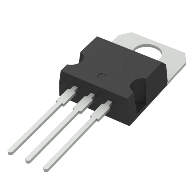
The three leads are on 0.100-inch pitch, and the tab is electrically connected to the drain. For rework, a standard soldering iron with a chisel tip can desolder the leads without lifting pads — the thermal mass of the tab requires a larger iron tip or a preheater to avoid cold joints on the tab solder point.
No official second-source or pin-compatible cross-reference is listed in the STMicroelectronics portfolio for this specific MDmesh M2-EP variant.