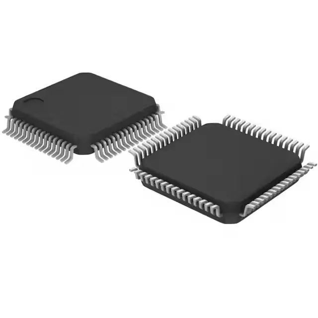
128 KB Flash, 24 MHz — the mid-range STM8S workhorse
What the 24 MHz and 128 KB Flash mean for the BOM
The 24 MHz clock speed is the ceiling for this 8-bit core — enough for UART polling at 115200 baud, sensor readout loops, and PWM generation at audio frequencies, but not for heavy DSP or real-time control loops that would push a Cortex-M0 at 48 MHz. The 128 KB Flash is the mid-density option in the STM8S207 line, sitting between 64 KB and 256 KB parts; it fits firmware images with a moderate protocol stack (e.g., Modbus RTU, CANopen) plus application code, but leaves no room for over-the-air update staging without external memory. The 6 KB RAM is tight for buffering — a single 2 KB UART receive buffer plus a 1 KB stack leaves 3 KB for variables. Designs that need larger packet buffers or multiple DMA descriptors should budget for an external SRAM or step up to the STM8S208 with more RAM. The 2 KB EEPROM is useful for calibration constants and configuration parameters that survive a firmware update, since it is separate from the Flash program space.
Peripheral set and sensor interface fit
The 16-channel 10-bit ADC covers a typical sensor array (temperature, pressure, current sense, potentiometer) without an external mux. The 52 I/O lines leave headroom for a parallel LCD data bus, keypad matrix, and several status LEDs alongside the serial interfaces. The built-in brown-out detect, POR, and watchdog reduce external supervisor IC cost on the BOM. Connectivity includes I²C and SPI for local peripherals (EEPROM, DAC, digital pot), plus UART/USART and LINbus for industrial fieldbus or automotive subnets. IrDA support is present but rarely used in new designs — it is a legacy compatibility feature.
Package, temperature grade, and supply rails
Supply voltage from 2.95V to 5.5V lets the MCU run directly on a 3.3V regulated rail or a 5V unregulated supply (e.g., from a USB port or an industrial 5V backplane).