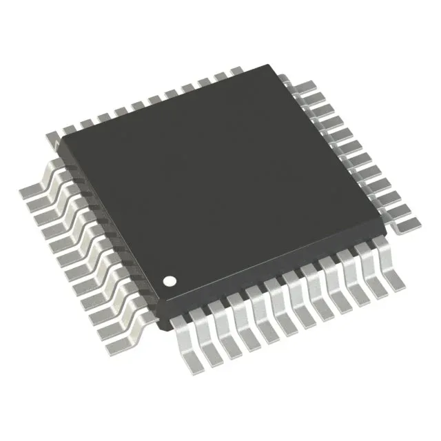
16 MHz core, 8 KB Flash — sizing the control loop
The supply range spans 2.95 V to 5.5 V, so it can run directly from a 5 V rail or a 3.3 V regulated supply without a separate I/O voltage.
125°C rating — where it survives
This part belongs in motor drives, engine-bay electronics, outdoor telecom gear, and factory-floor sensors where the ambient inside the enclosure can hit 85°C or higher. The 125°C ceiling also provides margin for self-heating in a sealed box. If your design lives in a conditioned room, a commercial-grade part may be cheaper; for anything that sees a hot dashboard or a sun-baked cabinet, this is the correct temperature tier.
Memory budget — what fits in 8 KB
Eight kilobytes of Flash is enough for a bootloader plus a modest application — think a sensor node polling a few channels, a brushless-DC motor commutation routine, or a LIN slave node. The 1 KB RAM handles a couple of moderate buffers and a small call stack. The 640-byte EEPROM is separate from the Flash and rated for 100k erase/write cycles (per the STM8S reference manual), so it can store calibration constants, fault logs, or configuration parameters without wearing out the program memory.
5 V tolerance — no level shifters needed
That means direct connection to 5 V sensors, 5 V logic outputs, and legacy peripherals without external level translators. The 4-channel 10-bit ADC also operates over the full supply range, so it can read a 0-5 V sensor signal directly when Vdd is 5 V. This simplifies the BOM and frees board space in cost-sensitive designs.
For dual-source resilience, note that the STM32L151CBU6A is a different architecture (32-bit ARM Cortex-M3) and not a pin-compatible drop-in; there is no second-source listed in the official cross-reference.