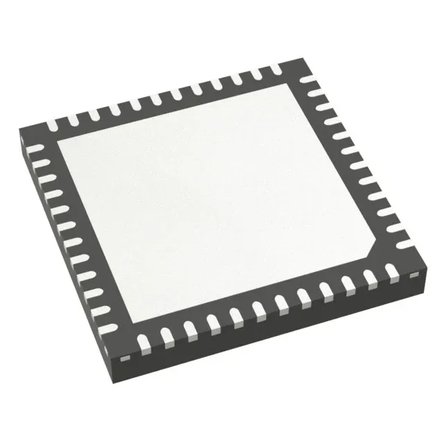
The 42 I/O in a 48-UFQFN exposed-pad package (7x7 mm footprint) keeps the BOM dense enough for a two-layer board if you route carefully.
Analog peripheral count — 21 ADC channels, 7 DAC channels
The data converter block is what distinguishes this part from a plain Cortex-M4: 21 multiplexed 12-bit SAR ADC channels and seven 12-bit DAC outputs. For a three-phase motor current-sense design you can sample all three shunt resistors plus the DC-link voltage and still have channels left for thermistor and encoder inputs. The seven DACs cover offset trim or reference generation without external op-amp stages. Brown-out detect, POR, and a true random number generator are on the peripheral list, so the watchdog and TRNG share the die rather than needing external supervisor ICs.
At the low end, 1.71 V is close to the dropout of a 1.8 V rail, so a battery-backed design can run the MCU until the cell is nearly flat.
Connectivity and debug access
CANbus, I²C, SPI, QSPI, SAI, UART/USART, IrDA, LINbus, and USB are all present. The QSPI interface lets you memory-map an external NOR Flash for code shadowing or data logging without chewing up GPIO for a parallel bus. SWD debug stays alive even with the watchdog armed — useful when the firmware is still unstable and you need to break into a hung loop without a hardware reset.
STMicroelectronics lists the STM32G473CEU3 as Active.