170 MHz Cortex-M4 with dedicated FPU and CORDIC — the mixed-signal control workhorse
The 23-channel 12-bit ADC and four 12-bit DAC channels let it handle multiple analog feedback signals without external converters.
The 128 KB program memory is sized for a moderate-complexity control stack — a motor-control library, a communication protocol stack, and a bootloader fit without overflow. The 32 KB SRAM (organized as 32K x 8) holds two or three PWM lookup tables, ADC sample buffers, and the RTOS task stacks. If the application needs more data memory, the part lacks an external memory interface; the firmware architect should budget the RAM against the sensor fusion or logging requirements early. The Flash is rated for the usual STM32G4 endurance — sufficient for OTA updates with wear-leveling in the application layer.
23-ch 12-bit ADC and 4-ch 12-bit DAC — analog density without external converters
The data converter block is the standout feature for mixed-signal designs. Twenty-three 12-bit ADC channels cover multi-phase current sensing, voltage feedback, and temperature monitoring on a single chip. The four 12-bit DAC channels can generate analog setpoints or offset compensation voltages directly. The ADC sampling rate and the DAC settling time are fast enough for inner current loops in digital power supplies running at 100 kHz+ switching frequencies.
Industrial temperature range and 80-LQFP package
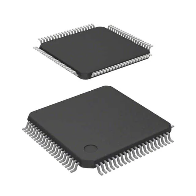
The 80-LQFP (12x12 mm) package with 66 I/O is a common footprint for medium-complexity control boards — hand-solderable for prototypes, and the exposed pad (if present on the variant) needs a thermal via stitch for heat dissipation when the core runs sustained 170 MHz with all peripherals active.
It is part of ST's mainstream G4 portfolio, which has a long-term commitment for industrial and consumer applications. The base product number STM32G431 covers multiple memory and package variants, so a BOM migration to a different density or footprint within the family is straightforward without a complete firmware rewrite.