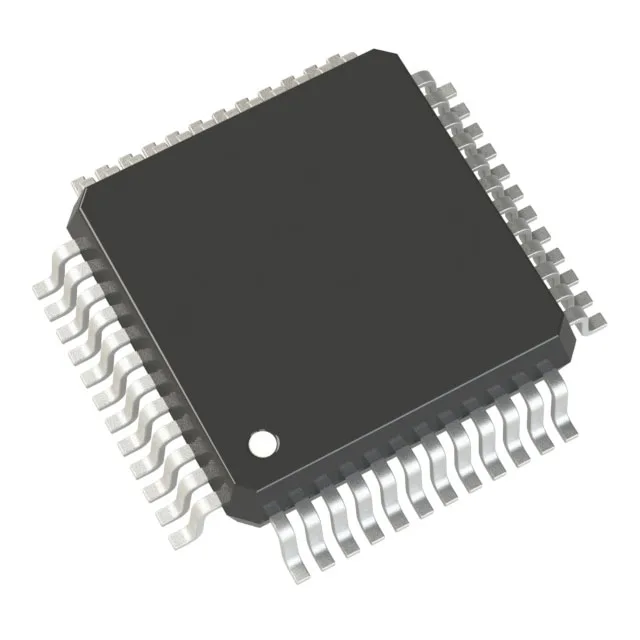
64 MHz Cortex-M0+ — what the speed buys the design
The STM32G031C8T6 runs the ARM Cortex-M0+ core at 64 MHz, which puts it in the upper tier of the M0+ performance range. For a control loop or sensor-fusion task, that clock rate translates to roughly 64 DMIPS — enough to handle a 10 kHz PID loop with margin for communications overhead. The flash wait state needs configuring at this speed; the datasheet recommends one wait state above 24 MHz, so the boot code should set it before the PLL locks.
Memory map: 64 KB Flash, 8 KB SRAM
Program memory is 64 KB of Flash, organized as 64 K x 8. The 8 KB SRAM (8 K x 8) is modest but adequate for a single control loop, a small RTOS tick, and a few communication buffers. If the firmware needs a large lookup table or a display frame buffer, the 64 KB Flash boundary is the hard limit — no external memory interface on this part. The Flash endurance is rated for the STM32G0 family standard; sector erase granularity is 2 KB, which matters when planning an OTA update region.
At 64 MHz the active current draw is typically in the 10–15 mA range, though the exact figure depends on peripheral usage.
Package and I/O count
All I/O are 5 V tolerant on this family, which simplifies level-shifting when interfacing to 5 V legacy peripherals.
The 1.7 V minimum supply holds across the full temperature range, so battery-powered outdoor sensors can run down to the cell's end-of-life voltage without a regulator dropout.