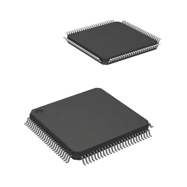
For a procurement desk, that means no urgency to stockpile or qualify a replacement — the supply channel is stable and the manufacturer continues to fab and test this code.
What the 72 MHz and 128 KB Flash mean for your BOM
The 72 MHz core clock is the practical ceiling for real-time control loops — sensor polling, PID updates, and communication stack processing all share this bandwidth. At this speed, the flash requires one wait state for zero-wait execution; the Cortex-M3 prefetch buffer helps keep the pipeline fed. The 128 KB Flash is the mid-density tier in the STM32F103 line; firmware that fits in 128 KB today leaves no headroom for major OTA updates or feature additions without a spin to a higher-density sibling. The 20 KB SRAM is the working memory for stack, heap, and DMA buffers — a USB descriptor set or a CAN message queue will consume several kilobytes, so budget the RAM allocation early in the firmware design.
80 I/O in a 100-LQFP — footprint and routing
The 100-pin LQFP (14x14 mm body) gives the designer 80 usable GPIOs. That is enough to drive a parallel LCD data bus, read a bank of sensors, and still have pins left for UART, SPI, and I²C without multiplexing.