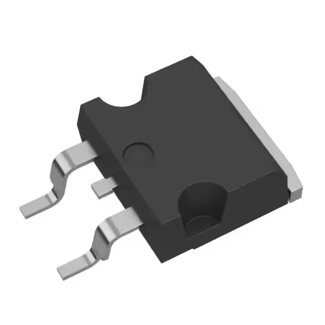
STH275N8F7-2AG

STMicroelectronics · Automotive, AEC-Q101, STripFET™ F7 Series

STMicroelectronics STripFET™ F7 series, Automotive AEC-Q101, N-Channel MOSFET, 80 V Vdss, 180 A Id, 2.1 mOhm Rds(on) @ 10 V, 193 nC Qg, H2Pak-2 (TO-263), -55°C to 175°C.

STMicroelectronics STH275N8F7-2AG
Download datasheet (PDF)
[IN STOCK] In Stock: 5 pcs
$16.23/ pc

Volume pricing

Buy Now

MOQ 1 · Tape & Reel (TR); Cut Tape (CT) · RoHS · EIA-481 · DAP/DDP · T/T

Technical specifications

STH275N8F7-2AG specifications
Parameter / AttributeSpecification / Value
SeriesAutomotive, AEC-Q101, STripFET™ F7
FET typeN-Channel
MountingSurface Mount
Drain to source voltage80 V
Drive voltage (Max rds on, min rds on)10V
Current - continuous drain (Id) @ 25°C180A (Tc)
Power dissipation315W (Tc)
Operating temperature-55°C ~ 175°C (TJ)
PackageTape & Reel (TR); Cut Tape (CT)
Vgs±20V
TechnologyMOSFET (Metal Oxide)
CaseTO-263-3, D²Pak (2 Leads + Tab), TO-263AB
Vgs(th) (Max) @ id4.5V @ 250µA
Rds on (Max) @ id, vgs2.1mOhm @ 90A, 10V
Gate charge (Qg) (Max) @ vgs193 nC @ 10 V
Input capacitance (Ciss) (Max) @ vds13600 pF @ 50 V

Technical details

Gate charge and switching — what the 193 nC Qg means for the driver

The STH275N8F7-2AG: A gate charge of 193 nC at 10 V is moderate for a die this size — it means the gate driver needs to source and sink that charge quickly to achieve fast switching. Pair this MOSFET with a driver rated for at least 2 A peak output current to keep turn-on and turn-off edges clean. PCB layout should minimise the gate-loop inductance between driver output and the H2Pak-2 gate pin.

Thermal budget — 315 W dissipation, but only with proper heatsinking

The H2Pak-2 (TO-263) package's exposed tab must be soldered to a large copper plane on the PCB or bolted to a metal chassis for thermal transfer.

It is RoHS3 compliant and available through independent distribution.

STH275N8F7-2AG
[ALLOC] verified
Quote