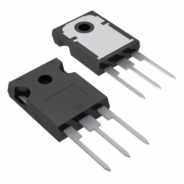
600 V, 60 A — the bus rating that decides the inverter
The STGWT30H60DFB is a 600 V, 60 A Trench Field Stop IGBT from STMicroelectronics, built for hard-switching power converters where conduction and switching losses both matter. The 600 V collector-emitter breakdown sets the maximum DC bus voltage — typically 300–400 VDC in a three-phase inverter — with margin for transients. The 60 A continuous collector current (120 A pulsed) defines the load current the device can handle with adequate heatsinking.
Switching losses and gate drive budget
Total gate charge is 149 nC — at a 10 kHz switching frequency the gate driver must supply 1.49 mA average, well within a standard IGBT driver. Switching energy is 383 µJ turn-on and 293 µJ turn-off under the test condition of 400 V, 30 A, 10 Ω gate resistor, 15 V gate drive. The 53 ns reverse recovery time on the co-packaged diode reduces the diode recovery loss contribution.
Conduction loss at rated current
At 30 A the conduction loss is 60 W — the 260 W maximum power dissipation in the TO-3P package requires a heatsink with a thermal resistance below about 2.5 °C/W to keep the junction under 175 °C.
Active production, no LTB watch needed
The TO-3P through-hole package is a long-lifecycle form factor, and the Tube shipping medium is straightforward to store without moisture sensitivity concerns.