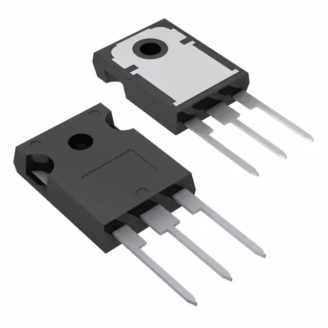
STMicroelectronics STGWA80H65FB

STGWA80H65FB IGBT, 650 V, 120 A, TO-247-3, Trench Field Stop

MPNSTGWA80H65FB
End of Life

STMicroelectronics STGWA80H65FB, Trench Field Stop IGBT, 650 V Vces, 120 A Ic, 469 W, TO-247-3 Long Leads, -55 to 175 °C.

$6.97Ref. price · indicative, final on quote
PackagingTO-247-3
StockContact for availability
MOQ1 pcs
  • 100% new & originalTraceable channels only — no refurbs, no pulls, no remarked parts.
  • Date & lot codes on quoteStated per line before you commit; label photos on request.
  • MSL-compliant ESD packingMoisture-sealed bags with indicator cards; reels photo-verified.
  • PayPal buyer protectionPay by T/T, PayPal or Payoneer — card payments covered end to end.

Specifications

STGWA80H65FB Technical Specifications
ParameterValue
IGBT typeTrench Field Stop
Input typeStandard
Mounting typeThrough Hole
Voltage - collector emitter breakdown650 V
Current - collector (Ic)120 A
Current - collector pulsed240 A
Power - max469 W
Operating temperature-55°C ~ 175°C (TJ)
PackageTube
Gate charge414 nC
CaseTO-247-3
Test condition400V, 80A, 10Ohm, 15V
Switching energy2.1mJ (on), 1.5mJ (off)
Td (on/off) @ 25°C84ns/280ns
Vce(on) (Max) @ vge, ic2V @ 15V, 80A

Product details

650 V, 120 A Trench Field Stop IGBT — switching-loss budget

The STGWA80H65FB is a 650 V, 120 A Trench Field Stop IGBT from STMicroelectronics in a TO-247-3 Long Leads package. It targets hard-switching applications such as motor drives, inverters, and power supplies where the 650 V breakdown and 120 A continuous collector current set the bus-voltage and load-current ceiling. The Trench Field Stop structure gives a low saturation voltage of 2 V at 15 V gate drive and 80 A, which directly reduces conduction loss in the on-state.

Switching energy and gate drive demand

Switching losses are characterised at 400 V, 80 A, 10 Ω gate resistor, and 15 V gate drive: 2.1 mJ turn-on and 1.5 mJ turn-off. At a 20 kHz switching frequency, the total switching loss at those conditions is roughly 72 W — a number that must be factored into the heatsink design alongside the 469 W maximum power dissipation. The 414 nC total gate charge means the gate driver must source about 8.3 mA average current at 20 kHz; a driver with insufficient peak current will stretch the switching times and increase loss.

Temperature range and package considerations

The TO-247-3 Long Leads package is a through-hole mount that simplifies heatsinking — the large tab area provides a low thermal resistance path to the heatsink. The 240 A pulsed collector current rating gives headroom for inrush and short-circuit events, but the SOA must be checked against the actual switching trajectory at the operating junction temperature.

Frequently asked questions

What is the maximum collector current of the STGWA80H65FB?

The maximum continuous collector current is 120 A, with a pulsed collector current rating of 240 A. Both figures are at the case temperature specified in the datasheet; derating applies at elevated junction temperatures.

What is the gate charge of the STGWA80H65FB?

The total gate charge is 414 nC. This value determines the average gate drive current needed at the target switching frequency.