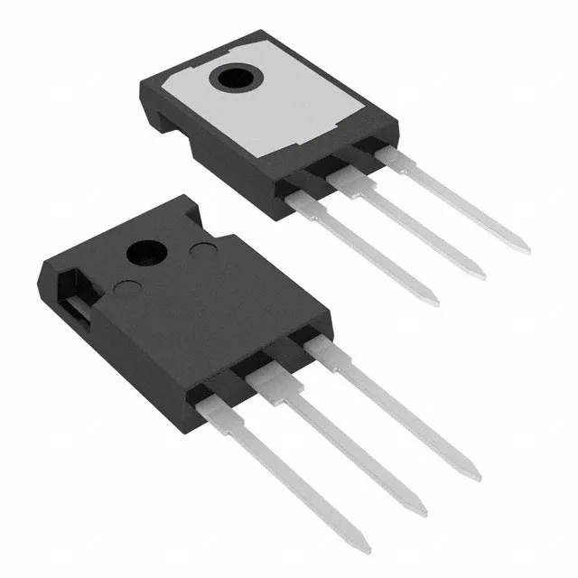
The STGWA15H120DF2 is a 1200 V, 30 A Trench Field Stop IGBT from STMicroelectronics in a TO-247-3 through-hole package. It is designed for medium-power hard-switching applications such as motor drives, solar inverters, welding machines, and uninterruptible power supplies where the DC-bus voltage typically runs 400 V to 800 V and the load current stays under 30 A continuous. The 1200 V collector-emitter breakdown voltage provides a 50% derating margin on a 600 V DC bus, covering transients and bus pumping during regenerative braking without avalanche stress.
Switching losses and thermal budget — the numbers that size your heatsink
Tested at 600 V, 15 A, 10 Ω gate resistor, and 15 V gate drive, the part switches 380 µJ on and 370 µJ off. At a 20 kHz switching frequency, that is roughly 15 W of switching loss before any conduction loss is added — a TO-247 package with a moderate heatsink handles that, but pushing toward 40 kHz requires a larger thermal interface or forced air. The 67 nC total gate charge means the gate driver needs to source and sink about 0.67 A peak at 15 V to hit the 23 ns turn-on and 111 ns turn-off delays — a standard 1 A to 2 A gate driver IC is sufficient. Maximum power dissipation is 259 W, but the practical limit is set by the junction-to-case thermal resistance and the operating junction temperature ceiling of 175°C — the 175°C Tj(max) gives more headroom than 150°C-rated IGBTs in high-ambient enclosures.
Package and mounting — TO-247-3 through-hole
The TO-247-3 package has a standard 5.45 mm pin pitch and uses a single mounting hole for screw-down to the heatsink. The collector tab is electrically live — an insulating pad and shoulder washer are required if the heatsink is grounded.