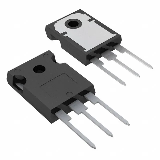
What this 1200 V Trench Field Stop IGBT is for
The STGW40M120DF3 is a 1200 V, 80 A continuous (160 A pulsed) Trench Field Stop IGBT from STMicroelectronics in a TO-247-3 through-hole package. With a 125 nC total gate charge and switching energies of 1.5 mJ on and 2.25 mJ off at 600 V, 40 A, it is sized for hard-switching applications in the 5–20 kHz range.
The 175°C Tj(max) gives headroom above the usual 150°C industrial limit, so the thermal design can push closer to the rated 468 W power dissipation without derating prematurely.
Switching performance at the test condition
The turn-on delay is 35 ns and turn-off delay is 140 ns at 25°C. The reverse recovery time of the internal diode is 355 ns. For a 20 kHz PWM cycle, the switching losses per pulse (1.5 mJ on, 2.25 mJ off) add up to about 75 W of switching loss at that frequency — the designer needs to budget that against the 468 W package limit and the junction temperature rise.
Package, mounting, and compliance
TO-247-3 through-hole — three leads, large tab for heatsink mounting. ROHS3 compliant per.