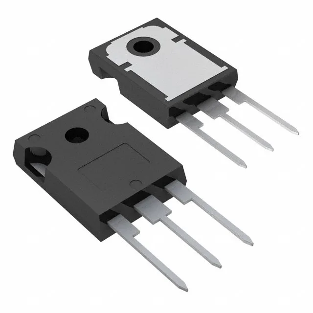
600 V, 60 A — the power-stage envelope
It targets hard-switching applications such as motor drives, UPS inverters, and PFC stages where the 600 V blocking voltage and 60 A continuous collector current define the power-stage headroom.
Switching losses and thermal budget
Switching energy is specified at 350 µJ (turn-on) and 435 µJ (turn-off) under the test condition of 480 V, 20 A, 10 Ω gate resistor, and 15 V gate drive. These numbers let you estimate dissipation at your operating frequency — for a 20 kHz hard-switched inverter, the per-cycle loss totals about 785 µJ, which at 200 W package maximum sets the thermal design constraint. Gate charge is 96 nC, which determines the drive current needed from the gate driver to meet the target switching speed. The 29 ns turn-on delay and 120 ns turn-off delay at 25°C are within the typical range for a 600 V trench IGBT in this current class.
The 40 ns reverse recovery time of the internal diode helps manage turn-on losses in hard-switched topologies. Pulsed collector current capability of 125 A gives headroom for short-duration overloads such as motor start or inrush events. The 2.7 V Vce(on) at 15 V gate drive and 20 A collector current is a typical on-state voltage for a 600 V trench IGBT at this current density.