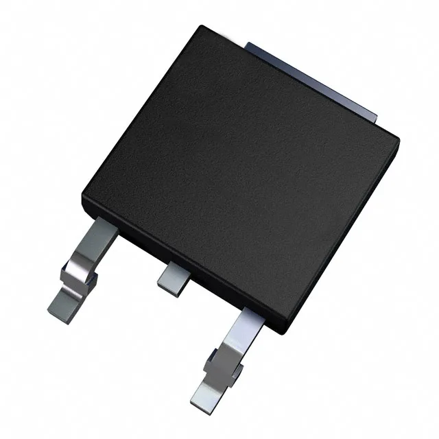
600 V, 20 A — the motor-drive and PFC sweet spot
It targets the 600 V class of inverter legs, PFC boost stages, and motor drives where the collector current ceiling of 20 A continuous (30 A pulsed) gives headroom for 1–2 kW power stages. The on-state voltage is specified at 2.5 V maximum at 15 V gate drive and 5 A collector current — the conduction loss at that operating point is 12.5 W, well within the 62 W package power limit when the DPAK is soldered to adequate copper area.
Switching losses and gate drive budget
Tested at 390 V, 5 A with a 10 Ohm gate resistor and 15 V gate drive, the part switches 55 µJ on and 85 µJ off per cycle. The 19 nC total gate charge means a standard gate-driver IC can drive it to 20–50 kHz without excessive drive current — a 19 nC gate at 50 kHz draws under 1 mA average from the driver supply. Turn-on delay is 17 ns and turn-off delay 72 ns at 25 °C, with a 22 ns reverse recovery time in the internal freewheeling diode. The diode's fast recovery keeps the switching node ringing under control in hard-switched topologies.
Active production, ROHS3 — no LTB risk
If a second-source requirement arises, the pin-compatible alternatives in the same PowerMESH™ family share the same tab-to-pin assignment — the layout does not need re-spinning.
DPAK layout and thermal notes
The 62 W maximum power rating assumes the tab is soldered to a minimum 1 oz copper pad with thermal vias to an inner plane; without that, the junction-to-ambient resistance limits continuous dissipation to well below the package limit. The wide temperature grade also suits outdoor telecom and solar-inverter applications where the enclosure sees ambient peaks above 85 °C.