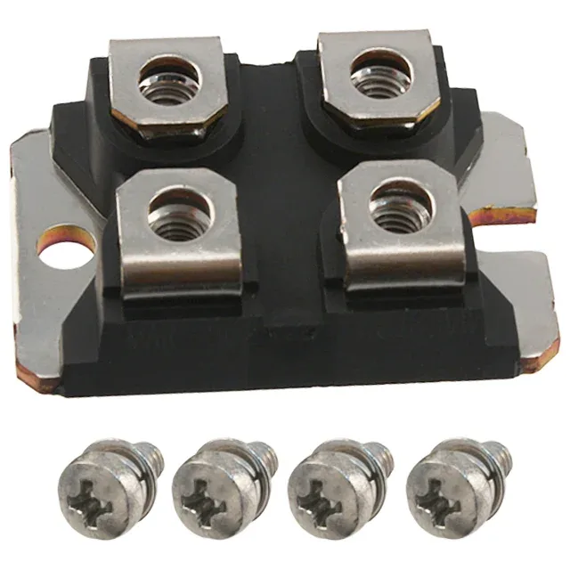
Bolting it down — ISOTOP chassis-mount reality
The STE145N65M5: The mounting method is chassis mount, not PCB solder; the buyer and layout engineer need to plan for a thermal interface material and a screw-torque spec, not a reflow profile.
650 V, 143 A, 15 mOhm — what the headline ratings mean for the power stage
The 15 mOhm maximum on-resistance at Vgs = 10 V and 69 A is the conduction-loss floor; at full current the dissipation in the die alone, before switching losses, is over 300 W, which is why the 679 W power dissipation rating at the case and the ISOTOP's thermal path to a heatsink are non-negotiable.
Gate charge — sizing the driver
The 414 nC total gate charge at Vgs = 10 V sets the gate-driver current requirement. At a 50 kHz switching frequency, the average gate-drive current is 414 nC × 50 kHz = 20.7 mA; at 100 kHz it doubles to 41.4 mA. The peak current capability of the driver must also handle the charging of the 18500 pF input capacitance at the switching edge — a standard 2 A or 4 A gate-driver IC is adequate, but a weak logic-output driver will stretch the switching times and increase cross-conduction losses.