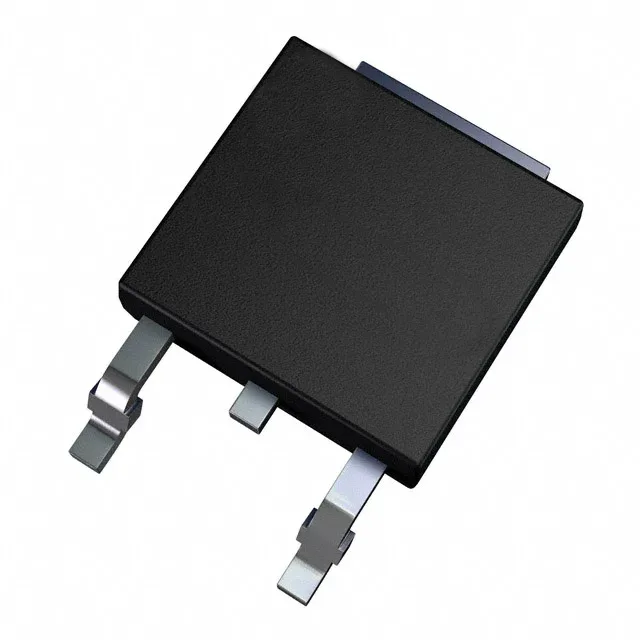
STMicroelectronics STD65N55F3 — Discrete Semiconductors

STD65N55F3 N-Channel MOSFET, 80A, 55V, 8.5mOhm

MPNSTD65N55F3
Active

STMicroelectronics STripFET™ STD65N55F3, N-Channel MOSFET, 55V Vdss, 80A Id, 8.5mOhm Rds(on) at 10V, DPAK (TO-252), -55°C to 175°C.

$2.3100Ref. price · indicative, final on quote
Independent supplier — new & surplus stockAuthenticity-screened · ESD-safe packingListing updated Aug 2026

Specifications

STD65N55F3 specifications
ParameterValue
SeriesSTripFET™
FET typeN-Channel
MountingSurface Mount
Drain to source voltage55 V
Drive voltage (Max rds on, min rds on)10V
Current - continuous drain (Id) @ 25°C80A (Tc)
Power dissipation110W (Tc)
Operating temperature-55°C ~ 175°C (TJ)
PackageTape & Reel (TR) Cut Tape (CT)
Vgs±20V
TechnologyMOSFET (Metal Oxide)
CaseTO-252-3, DPAK (2 Leads + Tab), SC-63
Vgs(th) (Max) @ id4V @ 250µA
Rds on (Max) @ id, vgs8.5mOhm @ 32A, 10V
Gate charge (Qg) (Max) @ vgs45 nC @ 10 V
Input capacitance (Ciss) (Max) @ vds2200 pF @ 25 V

Product details

80 A continuous drain, 8.5 mΩ Rds(on) — what it means for a switching design

The STMicroelectronics STD65N55F3 is an N-channel STripFET power MOSFET rated for 55 V drain-source breakdown and 80 A continuous drain current at a 25°C case temperature.

The 175°C maximum junction is the ceiling; the 110 W power dissipation rating assumes the case is held at 25°C, so real-world derating curves from the datasheet are the reference for any design that runs the junction above 100°C. The 4 V maximum gate threshold at 250 µA drain current means the device turns on fully with a standard 10 V gate drive, but the threshold window is wide enough that logic-level drive at 5 V may not guarantee full enhancement across temperature.

DPAK footprint and sourcing

The STD65N55F3 comes in a surface-mount DPAK (TO-252-3) package with two leads and a tab that serves as the drain connection and primary thermal path.

Frequently asked questions

What is the Rds(on) of STD65N55F3 at 10V gate drive?

The maximum Rds(on) is 8.5 mΩ at a 10 V gate drive with a 32 A drain current. This is the figure to use for worst-case conduction loss calculations in a switching regulator or motor drive.