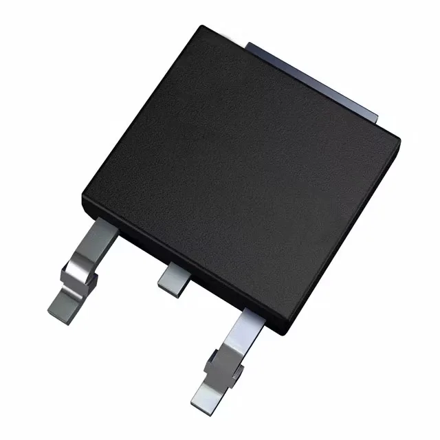
Gate drive and switching — what the 4.5 V / 10 V drive voltage tells you
The 65.5 nC typical gate charge at 10 V means the gate driver needs to source and sink that charge within the switching period; a 1 A driver will turn the FET on in about 65 ns, but the 3525 pF input capacitance at 25 V drain-source adds to the driver's reactive load. For PWM frequencies above 20 kHz, budget gate-drive power dissipation and switching losses in the total loss calculation.
Temperature range and qualification — where this part is used
For designs targeting ISO 26262 or customer-specific reliability programs, the AEC-Q101 lot traceability and PPAP documentation should be available from STMicroelectronics.