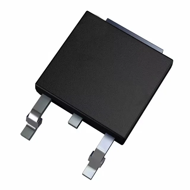
STMicroelectronics STD17NF25 — Discrete Semiconductors

STD17NF25 STMicroelectronics N-Ch MOSFET, 250 V, 17 A, DPAK

MPNSTD17NF25
Active

STMicroelectronics STripFET™ II N-Channel MOSFET, STD17NF25, 250 Vdss, 17 A Id, 165 mOhm Rds(on), DPAK (TO-252) surface mount, Tape & Reel.

$1.6500Ref. price · indicative, final on quote
PackagingTO-252-3, DPak (2 Leads + Tab), SC-63
RoHSROHS3 Compliant
SeriesSTripFET™ II
Independent supplier — new & surplus stockAuthenticity-screened · ESD-safe packingListing updated Aug 2026

Specifications

STD17NF25 specifications
ParameterValue
SeriesSTripFET™ II
FET typeN-Channel
MountingSurface Mount
Drain to source voltage250 V
Drive voltage (Max rds on, min rds on)10V
Current - continuous drain (Id) @ 25°C17A (Tc)
Power dissipation90W (Tc)
Operating temperature-55°C ~ 150°C (TJ)
PackageTape & Reel (TR) Cut Tape (CT)
Vgs±20V
TechnologyMOSFET (Metal Oxide)
CaseTO-252-3, DPak (2 Leads + Tab), SC-63
Vgs(th) (Max) @ id4V @ 250µA
Rds on (Max) @ id, vgs165mOhm @ 8.5A, 10V
Gate charge (Qg) (Max) @ vgs29.5 nC @ 10 V
Input capacitance (Ciss) (Max) @ vds1000 pF @ 25 V

Product details

250 V, 17 A switching load ceiling

The STD17NF25 is an N-channel power MOSFET from STMicroelectronics' STripFET™ II series, rated for 250 V drain-source breakdown and 17 A continuous drain current at 25°C case temperature. This puts it in the medium-voltage, moderate-current class — suitable for switching loads in offline power supplies, DC-DC converters, and motor pre-drive stages where the bus rail sits at 48 V to 150 V and the peak current stays under the 17 A ceiling.

Conduction loss and gate drive budget

Maximum on-resistance is 165 mOhm at 8.5 A drain current with a 10 V gate drive. At 17 A the Rds(on) will be higher due to self-heating — the 90 W power dissipation limit at the case is the thermal budget that governs the real-world current derating. The 29.5 nC total gate charge at 10 V means the gate driver must supply roughly 2.95 mA per 100 kHz of switching frequency just to charge the gate capacitance; the 1000 pF input capacitance at 25 V drain-source adds to the switching loss calculation.

DPAK thermal and mounting

Housed in the DPAK (TO-252) surface-mount package with an exposed drain tab. The tab must be soldered to a copper pad on the PCB — the thermal resistance to ambient depends on the board's copper area and layer count. The -55°C to 150°C junction temperature range covers industrial ambient and under-hood automotive environments, but the 150°C upper limit means the thermal design must keep the junction below that at full load.

Frequently asked questions

What is the gate charge and what does it mean for my gate driver?

The total gate charge is 29.5 nC at 10 V gate drive. At a 100 kHz switching frequency, the average gate-drive current is about 2.95 mA — well within the capability of most dedicated MOSFET drivers, but a microcontroller GPIO driving directly may struggle to source that current at the required rise time.

Will STD17NF25 drop into a board designed for STD17NF03LT4?

No. The STD17NF03LT4 is a 30 V device with a different Rds(on) and gate charge profile. The STD17NF25 is rated for 250 V drain-source — the pinout and package (DPAK) are the same, but the 250 V rating means the board's clearance and creepage must support the higher voltage. A direct swap without verifying the circuit's voltage stress is not recommended.