STD140N6F7

STMicroelectronics

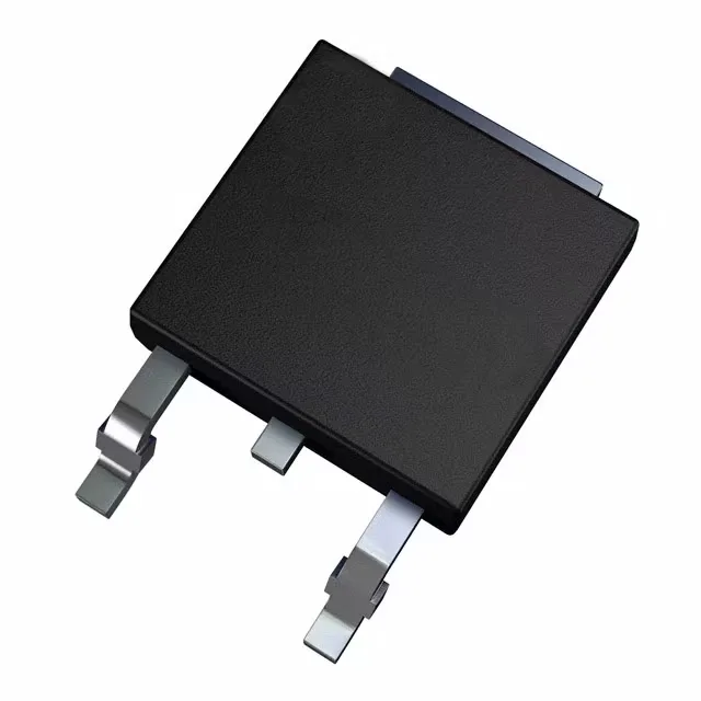
STMicroelectronics STripFET™ STD140N6F7, N-Channel MOSFET, 60 V Vdss, 80 A Id, 3.8 mOhm Rds(on) @ 40 A, 10 V, 55 nC Qg, DPAK, -55 to 175 °C.

STMicroelectronics STD140N6F7
Download datasheet (PDF)
[IN STOCK] In Stock: 6 pcs
$2.69/ pc

Volume pricing

Buy Now

MOQ 1 · Tape & Reel (TR); Cut Tape (CT) · RoHS · EIA-481 · DAP/DDP · T/T

Technical specifications

STD140N6F7 specifications
Parameter / AttributeSpecification / Value
SeriesSTripFET™
FET typeN-Channel
MountingSurface Mount
Drain to source voltage60 V
Drive voltage (Max rds on, min rds on)10V
Current - continuous drain (Id) @ 25°C80A (Tc)
Power dissipation134W (Tc)
Operating temperature-55°C~175°C(TJ)
PackageTape & Reel (TR); Cut Tape (CT)
Vgs±20V
TechnologyMOSFET (Metal Oxide)
CaseTO-252-3, DPak (2 Leads + Tab), SC-63
Vgs(th) (Max) @ id4V @ 250µA
Rds on (Max) @ id, vgs3.8mOhm @ 40A, 10V
Gate charge (Qg) (Max) @ vgs55 nC @ 10 V
Input capacitance (Ciss) (Max) @ vds3100 pF @ 30 V

Technical details

It is designed for low-voltage, high-current switching applications such as synchronous rectification, DC-DC converters, motor drives, and battery management in industrial and automotive environments.

Rds(on) and current rating — sizing the conduction path

The 80 A continuous drain current rating at 25°C case temperature gives substantial headroom for surge or inrush events, but the designer must derate the current based on the actual case temperature — the 134 W power dissipation limit (Tc) governs the safe operating area.

Gate charge and input capacitance — what they mean for switching speed

The input capacitance also sets the Miller plateau duration, which directly affects turn-on and turn-off switching losses.

Temperature range and package — deployment context

The maximum gate-source voltage is ±20 V, so standard 10 V gate drives are safe.

STD140N6F7
[ALLOC] verified
Quote