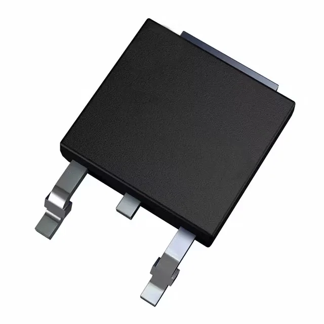
100 V, 13 A N-channel in DPAK — what this part is
The 21 nC typical gate charge and 460 pF input capacitance place it in the mid-speed class — fast enough for a 50–200 kHz hard-switched converter without demanding a high-current gate driver.
130 mOhm on-resistance — sizing the conduction loss
The 130 mOhm maximum Rds(on) is specified at 5 A drain current with a 10 V gate-source voltage. At 13 A full load, conduction loss calculates to about 22 W at the rated current — which means the 50 W package dissipation limit at case temperature is the real constraint, not the silicon. For a 3 A load in a 48 V telecom brick, the conduction loss drops to about 1.2 W, which the DPAK handles with a reasonable copper area on the drain tab.
DPAK package — thermal and assembly notes
The STD10NF10T4 comes in the DPAK (TO-252-3) surface-mount package with two leads and a tab. For continuous operation above 5 A, a 1-inch-square copper pour on the top layer with via stitching to an inner-layer plane is typical. The DPAK footprint is shared across many 100 V N-channel parts, so a second-source layout is straightforward.