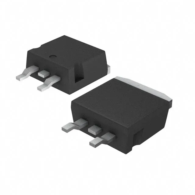
STMicroelectronics STB80NF10T4

STB80NF10T4 N-Channel MOSFET, 100 V, 80 A, D2PAK

MPNSTB80NF10T4
End of Life

STMicroelectronics STripFET™ II, STB80NF10T4, N-Channel MOSFET, 100 V Vdss, 80 A Id, 15 mOhm Rds(on) at 40 A, 10 V, D2PAK (TO-263), -55 to 175 °C.

$3.32Ref. price · indicative, final on quote
PackagingTO-263-3, D2PAK (2 Leads + Tab), TO-263AB
RoHSROHS3 Compliant
SeriesSTripFET™ II
Independent supplier — new & surplus stockAuthenticity-screened · ESD-safe packingListing updated Jul 2026

Specifications

STB80NF10T4 specifications
ParameterValue
SeriesSTripFET™ II
FET typeN-Channel
MountingSurface Mount
Drain to source voltage100 V
Drive voltage (Max rds on, min rds on)10V
Current - continuous drain (Id) @ 25°C80A (Tc)
Power dissipation300W (Tc)
Operating temperature-55°C ~ 175°C (TJ)
PackageTape & Reel (TR); Cut Tape (CT)
Vgs±20V
TechnologyMOSFET (Metal Oxide)
CaseTO-263-3, D2PAK (2 Leads + Tab), TO-263AB
Vgs(th) (Max) @ id4V @ 250µA
Rds on (Max) @ id, vgs15mOhm @ 40A, 10V
Gate charge (Qg) (Max) @ vgs182 nC @ 10 V
Input capacitance (Ciss) (Max) @ vds5500 pF @ 25 V

Product details

100 V, 80 A N-channel — the thermal budget sets the real current

The 15 mOhm on-resistance at 40 A, 10 V drive defines the conduction loss floor — at 80 A the I²R loss is 96 W before you add switching losses, so the 300 W power dissipation ceiling is real headroom only with a substantial heatsink and forced airflow.

Gate charge and drive current — what 182 nC means for the gate driver

Total gate charge is 182 nC at 10 V. At 100 kHz switching frequency the average gate drive current is 182 nC × 100 kHz = 18.2 mA, well within a standard gate driver's capability. The input capacitance of 5500 pF at 25 V drain-source sets the Miller plateau slope — a driver with at least 2 A peak source/sink keeps the switching edges clean and avoids partial turn-on during the Miller region.

175 °C junction — rated for the hot end of the motor drive

The D2PAK (TO-263) surface-mount package lets the exposed tab solder directly to a copper island on the PCB — the thermal resistance to ambient depends on that copper area, not the package itself.

Frequently asked questions

What is the gate charge of STB80NF10T4?

That figure drives the gate driver current requirement for a given switching frequency.

What is the maximum drain current of STB80NF10T4?

Continuous drain current is 80 A at 25 °C case temperature. Derate for higher ambient — the package thermal resistance and heatsinking determine the real limit.