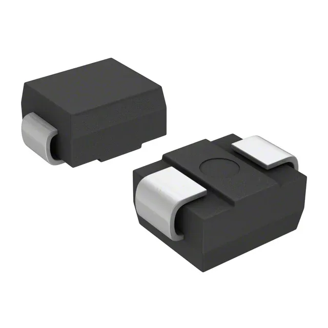
40V rail protector in a DO-214AA SMB package
Its 40V reverse standoff voltage means the diode stays off below that level, so it won't leak or conduct during normal operation on a 40V bus. When a surge hits, it clamps at a maximum 64.5V — that is the peak voltage the downstream circuitry must survive. The 600W peak pulse power rating (10/1000µs waveform) tells you how much transient energy it can absorb in a single event; for higher-energy surges you step up to the SMCJ or 1.5KE series.
Clamping voltage and standoff — the two numbers that matter
When you spec a TVS for a 40V rail, the standoff voltage is the first check: it must be at or above the maximum DC operating voltage so the diode does not conduct during normal bias. The clamping voltage is the second: every component on that rail must be rated to survive 64.5V for the duration of the transient. If your downstream parts are 60V-rated, this clamp leaves only 4.5V of headroom — consider a lower-clamping TVS or a higher-voltage downstream rating. The 9.7A peak pulse current (10/1000µs) is the current that flows at the clamping voltage; verify your PCB trace width and via count can handle that pulse without fusing.