Why the SM15T6V8AY exists — the 5.8 V rail protection gap
The breakdown voltage starts at 6.45 V, so it stays out of the way during normal operation and only conducts when the rail exceeds that threshold.
AEC-Q101 — the automotive gate
For a buyer specifying a TVS for an ECU, ADAS sensor module, or battery management system, the Q101 cert is the difference between a part that can be placed on the BOM without a waiver and one that requires an exception.
Voltage window — where it clamps and where it stays off
Three numbers define the protection window. The reverse standoff voltage is 5.8 V — the maximum continuous DC voltage the TVS can see without conducting appreciably. Below that, it looks like an open circuit. The minimum breakdown voltage is 6.45 V, so the part starts to avalanche when the rail rises about 11% above nominal. At the peak pulse current of 746 A (8/20 µs waveform), the clamping voltage reaches 13.4 V. The designer's margin check: ensure the clamped voltage stays below the absolute maximum rating of the IC being protected, and that the standoff voltage is at least 10% above the nominal rail to avoid nuisance triggering.
Package and footprint — DO-214AB (SMC)
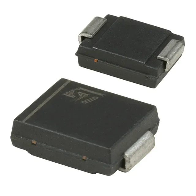
The SM15T6V8AY comes in a DO-214AB (SMC) surface-mount package. The SMC body is larger than the smaller SMA/SMB packages, which is necessary to dissipate the 1500 W pulse without exceeding the junction temperature. The PCB layout needs a solid thermal connection to the copper pour — the package relies on the board's copper area to sink the transient heat. A typical footprint uses a 4.5 mm by 4.0 mm pad per terminal, with vias to inner-layer planes if the board has them. The unidirectional channel means the cathode band on the package must be oriented toward the protected rail, with the anode to ground.