1-Kbit serial EEPROM with Microwire — BOM-fit note
The M93C46-WMN6TP is a 1-Kbit serial EEPROM from STMicroelectronics, organized as 128 x 8 bits or 64 x 16 bits, selectable via the ORG pin. It communicates over a standard Microwire bus at up to 2 MHz, making it a drop-in replacement for legacy 93C46 footprints in industrial and embedded designs. Supply voltage spans 2.5 V to 5.5 V, so the same part works on a 3.3 V microcontroller rail or a 5 V legacy bus without a level translator on the supply line. Operating temperature range is -40°C to +85°C — industrial grade, suited for outdoor telecom cabinets, motor-drive control boards, and automotive cabin-zone modules where the ambient stays below the +85°C ceiling.
Package and supply-chain reality
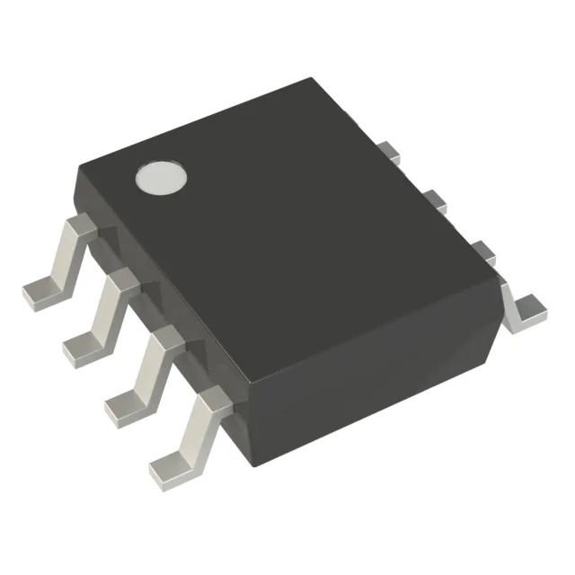
Housed in the industry-standard 8-SOIC (3.90 mm width) footprint, the M93C46-WMN6TP is offered on Tape & Reel (TR) and Cut Tape (CT) — the reel option suits automated pick-and-place for volume builds, while cut tape works for prototyping or small-batch rework. Lifecycle status is Active with full RoHS3 compliance (no exemptions expiring). No stock-holding claim — each lot is verified for traceability and RoHS compliance before dispatch.
Write timing and interface — firmware planning note
Write cycle time is 5 ms for a word or page — budget this into the firmware write routine. A single-byte write followed by a 5 ms polling delay is typical; a page write (up to 16 bytes in the 128 x 8 organization) still completes in the same 5 ms window, so batching writes improves throughput. The Microwire interface uses a dedicated Chip Select (CS), Serial Clock (SK), Data In (DI), and Data Out (DO) — four wires, no address/data multiplexing. The 2 MHz clock rate yields a raw read throughput of 2 Mbit/s, though the 5 ms write cycle dominates overall latency in a write-heavy application.