Automotive 64Kbit EEPROM for the 125°C bus
It organizes memory as 8K x 8 bits and communicates at a clock frequency of 1 MHz with a 450 ns access time. The supply voltage range spans 1.8V to 5.5V, covering both legacy 5V controller buses and modern 1.8V or 3.3V MCU rails without external level translation.
AEC-Q100 qualification and the 125°C operating ceiling
This part carries AEC-Q100 qualification, the automotive stress test sequence that covers extended temperature cycling, high-temperature operating life, and ESD robustness. For a calibration or verification technician tracking a reference value over temperature, the 125°C ceiling means the EEPROM retains data and write integrity through solder reflow profiles and under-hood thermal soak — no derating needed for the upper end of the automotive range.
Supply voltage and write-cycle timing for the BOM
At 1.8V the part still meets the 1 MHz clock and 450 ns access time, so a low-voltage MCU does not sacrifice bus speed. The write cycle time — 4 ms for a word or page write — sets the non-volatile commit latency. For a firmware engineer handling calibration parameters or fault logs, that 4 ms window means the write must complete before the system powers down or the watchdog resets the bus.
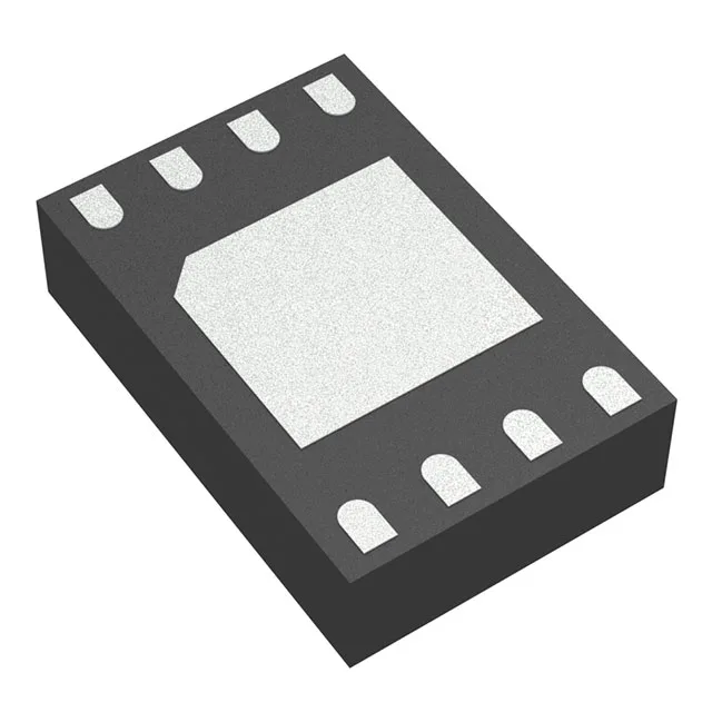
Package and footprint: 8-MLP (2x3 mm)
The device is supplied in an 8-WFDFN exposed-pad package, designated as 8-MLP (2x3 mm) by the supplier device package field. For a rework technician, the 2x3 mm body is small enough for a hot-air nozzle but the exposed pad needs a stencil aperture that covers the pad area without bridging the peripheral leads. Moisture sensitivity level is not stated in this record, so standard MSL 3 handling is the conservative assumption for bake-before-reflow decisions.
ROHS3 compliance is confirmed. No replacement or successor is indicated — the part is current-production for new designs.