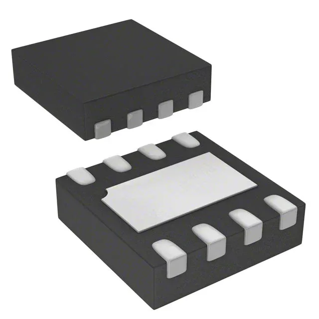
STMicroelectronics M24C04-FMB5TG, 4Kbit I2C EEPROM, 400kHz
STMicroelectronics M24C04-FMB5TG, 4Kbit I2C EEPROM, 512x8 organization, 400kHz clock, 1.7-5.5V supply, -20C to 85C, 8-UFDFPN (2x3) exposed-pad package, 5ms write cycle.
- 100% new & originalTraceable channels only — no refurbs, no pulls, no remarked parts.
- Date & lot codes on quoteStated per line before you commit; label photos on request.
- MSL-compliant ESD packingMoisture-sealed bags with indicator cards; reels photo-verified.
- PayPal buyer protectionPay by T/T, PayPal or Payoneer — card payments covered end to end.
Specifications
| Parameter | Value |
|---|---|
| Memory type | Non-Volatile |
| Mounting type | Surface Mount |
| Voltage | 1.7V ~ 5.5V |
| Frequency | 400 kHz |
| Memory interface | I²C |
| Operating temperature | -20°C ~ 85°C (TA) |
| Package | Tape & Reel (TR) |
| Technology | EEPROM |
| Access time | 900 ns |
| Memory size | 4Kbit |
| Memory format | EEPROM |
| Case | 8-UFDFN Exposed Pad |
| Memory organization | 512 x 8 |
| Write cycle time - word, page | 5ms |
Frequently asked questions
What I2C clock speed does this EEPROM support, and does the 5ms write cycle fit a typical Cortex-M firmware budget?
The bus runs at up to 400 kHz. The 5ms write cycle per page is the figure that matters — a blocking write holds the bus for that duration, so a firmware loop that polls the ack bit without yielding will stall for the full page write time. Restructure as interrupt-driven or split writes into shorter operations if the main loop has cycle hard limits.
The board runs on 3.3V — is there enough supply headroom for this part?
1.7 V to 5.5 V operating range means 3.3 V is well within the window. Under load transients the rail stays safely above the lower limit; the UFDFPN package does not create a thermal issue at EEPROM access currents on a 3.3 V rail.