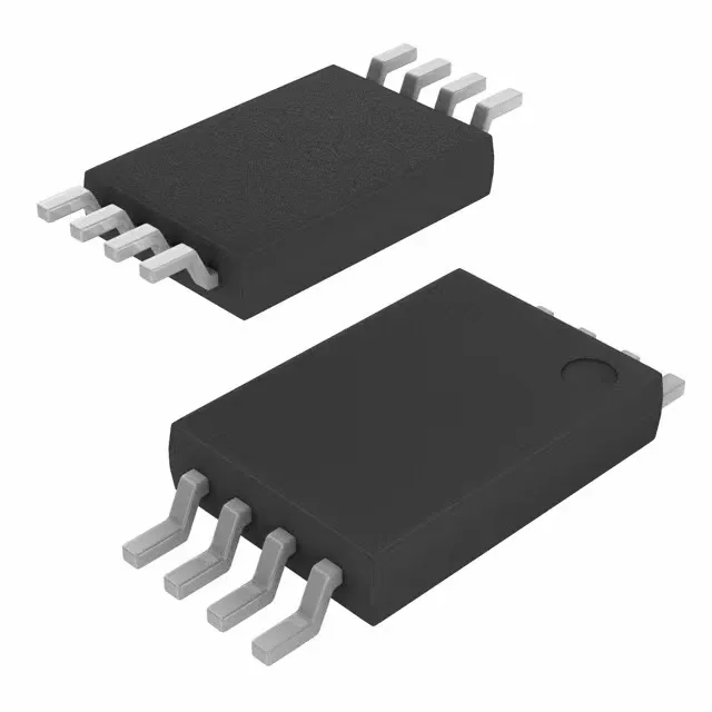
The STMicroelectronics M24C02-RDS6TG is a 2 Kbit serial EEPROM organized as 256 x 8 bits, accessed through an I2C interface at clock frequencies up to 400 kHz. The 900 ns access time defines the read-cycle latency on the bus — at 400 kHz the bus itself is the bottleneck, not the memory. The 8-MSOP package is a compact surface-mount footprint suited for space-constrained PCBs in industrial control, sensor modules, and embedded systems where a small non-volatile parameter store or calibration table is needed.
This part carries an official product status of Obsolete. STMicroelectronics has discontinued production, and no last-time-buy window is indicated in the available records. For a BOM line that currently specifies the M24C02-RDS6TG, the immediate decision is whether a pin-compatible drop-in exists or a board spin is required. The base product number M24C02 covers a family of 2 Kbit I2C EEPROMs in multiple packages (SOIC, TSSOP, UFDFPN) and temperature grades — a same-function variant in a different package may be easier to source, but the 8-MSOP package itself is the constraint. If the board layout can accommodate a slightly larger footprint, the M24C02 family in SOIC-8 or TSSOP-8 remains widely available through standard distribution.
The I2C interface is open-drain, so the bus pull-up resistors set the logic-high voltage — the device's own VCC determines its input thresholds. At 1.8 V operation, the access time and write cycle remain within spec, though the bus speed may be limited by the RC time constant of the pull-ups and trace capacitance. For a design migrating from 5 V to 3.3 V, this part eliminates one voltage translation component.
8-MSOP package — rework and layout notes
It reflows well with standard lead-free profiles, but the small pad size and tight pitch make hand-soldering tricky — a hot-air station with a fine nozzle is the practical method for rework. For layout, keep the I2C pull-up resistors close to the device to minimize stub length, and route the supply trace with enough width for the low DC current (microamps in standby, a few mA during write).