16 A RMS, 600 V — the load-switching ceiling
The BTA16-600CRG is a standard triac rated for 16 A RMS on-state current and 600 V off-state blocking voltage. That 16 A figure is the continuous current limit through the main terminals when the triac is fully on — it sets the maximum load you can switch, whether it's a resistive heater, an incandescent lamp bank, or a small motor. The 600 V off-state rating covers 230 VAC mains with comfortable margin, and even 400 VAC line-to-line in three-phase systems if the phase-to-phase voltage stays under the peak repetitive voltage. This is a standard-gate triac, meaning the gate trigger current (Igt) is 25 mA max and the holding current (Ih) is also 25 mA max. That's the conventional sensitivity level — it needs a stronger drive pulse than a logic-level or sensitive-gate triac, but it's also less prone to false triggering from noise on the gate line. The gate trigger voltage (Vgt) is 1.3 V max, so a standard 5 V logic output through a current-limiting resistor will drive it, though a dedicated gate driver or optotriac is the usual practice for isolation.
Surge current and fuse coordination
The non-repetitive surge current rating is 160 A at 50 Hz and 168 A at 60 Hz (half-cycle sine wave). This is the peak current the triac can withstand once without damage — it's the number you use when selecting the upstream fuse or circuit breaker. A fast-acting fuse rated below 160 A will clear before the triac fails short, protecting the load and the board. The surge rating also matters for capacitive loads (like LED drivers with large input caps) that draw a high inrush on power-up. The junction temperature range is -40°C to 125°C, which is the industrial temperature grade. At the high end, the on-state voltage drop increases and the surge capability derates — the datasheet's thermal impedance curve tells you how much heatsink you need to keep Tj under 125°C at 16 A continuous. At -40°C, the gate trigger current may rise slightly, but the 25 mA max spec is guaranteed across the full range.
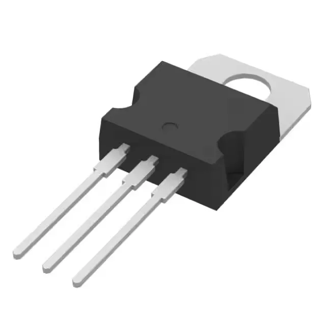
TO-220-3 — the standard through-hole power package
The three leads are MT1, MT2, and gate — the metal tab is electrically connected to MT2, so if you mount it to a grounded heatsink you need an insulating pad and bushing. The through-hole leads are 0.025-inch square pins on 0.100-inch pitch, fitting standard 0.040-inch diameter PCB holes. The package is delivered in tube, not tape-and-reel, which is typical for through-hole power devices. For a 16 A continuous load, expect to bolt this to a heatsink with thermal resistance below 4°C/W to keep the junction under 125°C in a 50°C ambient. The TO-220 tab is the primary heat path — the PCB copper alone won't sink 16 A without the junction exceeding the limit.