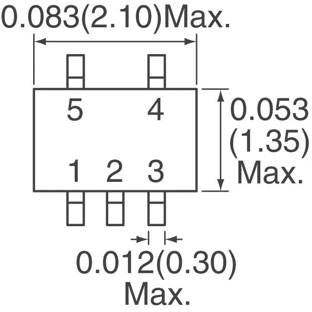
The ROHM UMG8NTR is a dual NPN transistor array with integrated bias resistors — each transistor has a 4.7 kΩ series base resistor (R1) and a 47 kΩ resistor (R2) between base and emitter. This pre-biased configuration eliminates two external resistors per channel, shrinking the BOM and board area for low-current switching applications up to 100 mA collector current and 50 V collector-emitter breakdown. The 250 MHz transition frequency means it handles moderate-speed switching — think relay drivers, LED indicators, logic-level translators, or sensor readout muxes — not RF or high-frequency power conversion. It comes in a 5-pin UMT5 package (SOT-353 footprint), surface-mount only. The 150 mW power ceiling keeps it in the low-signal domain; don't plan on driving a solenoid or motor winding directly.
Bias resistor ratio — the input threshold decision
With R1 at 4.7 kΩ and R2 at 47 kΩ, the base sees about 90% of the applied input voltage after the divider. A 3.3 V logic signal turns the transistor on hard — the VCE(sat) is only 300 mV at 5 mA with 250 µA base drive. If your logic level is 1.8 V, check the base current: at 1.8 V input, base current is roughly (1.8 V – 0.7 Vbe) / 4.7 kΩ ≈ 234 µA, still enough to saturate at 5 mA. Below 1.5 V input the margin gets thin.