ROHM Semiconductor UMG11NTR — Memory (DRAM / SRAM / Flash / EEPROM)

UMG11NTR Dual NPN Pre-Biased Transistor, 50V, 100mA, UMT5

MPNUMG11NTR
End of Life

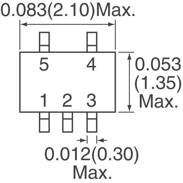
ROHM Semiconductor UMG11NTR, Dual NPN Pre-Biased Digital Transistor, 50V Vce, 100mA Ic, 150mW, 250MHz ft, Built-in R1=2.2kΩ, R2=47kΩ, UMT5 Surface-Mount Package.

$0.45Ref. price · indicative, final on quote
Packaging5-TSSOP, SC-70-5, SOT-353
StockContact for availability
MOQ1 pcs
  • 100% new & originalTraceable channels only — no refurbs, no pulls, no remarked parts.
  • Date & lot codes on quoteStated per line before you commit; label photos on request.
  • MSL-compliant ESD packingMoisture-sealed bags with indicator cards; reels photo-verified.
  • PayPal buyer protectionPay by T/T, PayPal or Payoneer — card payments covered end to end.

Specifications

UMG11NTR Technical Specifications
ParameterValue
Mounting typeSurface Mount
FET type2 NPN - Pre-Biased (Dual)
Voltage - collector emitter breakdown50V
Current - collector (Ic)100mA
Current - collector cutoff500nA
DC current gain (hFE) (Min) @ ic, vce80 @ 10mA, 5V
Power - max150mW
Frequency250MHz
PackageTape & Reel (TR); Cut Tape (CT)
Case5-TSSOP, SC-70-5, SOT-353
Resistor - base (R1)2.2kOhms
Resistor - emitter base (R2)47kOhms
Vce saturation (Max) @ ib, ic300mV @ 250µA, 5mA

Product details

Built-in bias resistors — one less component per channel

The UMG11NTR packs two NPN pre-biased transistors, each with a 2.2 kΩ series base resistor (R1) and a 47 kΩ resistor from base to emitter (R2), into a single UMT5 package. That means you drop the two external resistors per transistor that a standard NPN pair would need — four components saved on the bill of materials. The bias network sets a defined off-state and a predictable turn-on threshold, so the part works as a simple switch or inverter without extra biasing circuitry.

Switching performance and drive requirements

Collector current is rated to 100 mA continuous, with a Vce breakdown of 50 V — enough for 5 V or 12 V logic-level loads, relay drivers, or LED strings. The transition frequency of 250 MHz indicates the internal die can switch fast, but the built-in resistors limit the base drive; expect practical switching speeds in the low-MHz range for saturated operation. Vce(sat) is specified at 300 mV maximum with 250 µA base drive into 5 mA collector current, so the voltage drop stays low in lightly loaded digital outputs or level shifters.

Lifecycle — active, no last-time-buy concerns

ROHM lists the UMG11NTR with an active product status.

Frequently asked questions

What are the built-in resistor values (R1/R2) for UMG11NTR?

The base resistor (R1) is 2.2 kΩ, and the base-emitter resistor (R2) is 47 kΩ. These values set the input threshold and ensure the transistor is off when the base is open or low.

Can UMG11NTR replace a standard transistor with external resistors?

Yes, in many switching applications. The built-in 2.2 kΩ base resistor and 47 kΩ base-emitter resistor eliminate the need for external bias components. Check that the resulting base current (roughly (Vin - 0.7 V) / 2.2 kΩ) and the forced beta (Ic / Ib) meet your circuit's drive requirements.