What the bias resistors buy you
The UMB10NTN: That pair sets the base drive and off-state leakage for a common-emitter switch — you drop the two external resistors per channel from the BOM, saving board area and placement cost. With a collector current rating of 100 mA and a Vce breakdown of 50 V, this part handles typical 24 V or 48 V signal-level loads — relay coils, LED indicators, logic-level interfacing — without needing a separate driver transistor.
Switching speed and package reality
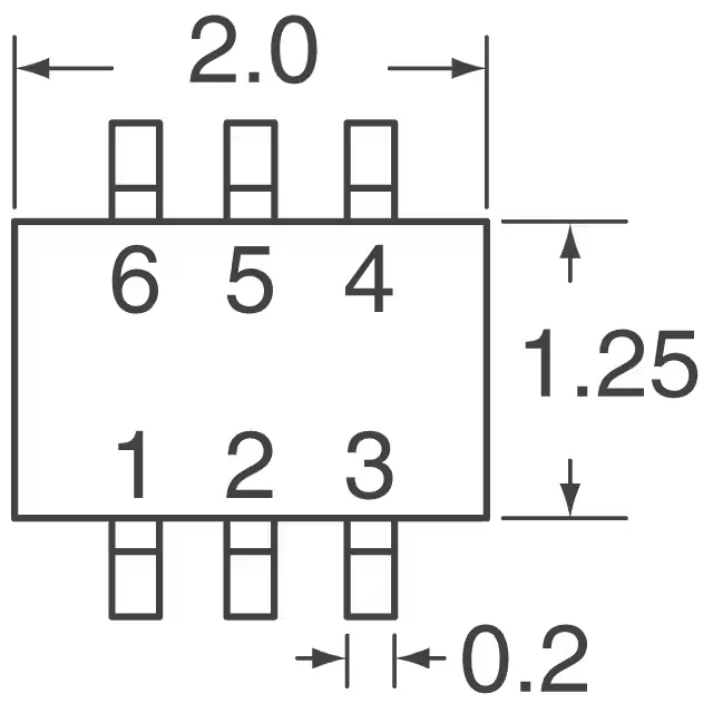
The 250 MHz transition frequency means the internal capacitance charges fast enough for PWM up to a few MHz, but the real switching edge is limited by the bias resistor network and the load capacitance. At 10 mA collector current the minimum hFE is 80 — plenty of gain to saturate the transistor with a microcontoller GPIO through the 2.2 kOhm base resistor. The SOT-363 (UMT6) package is 2.0 x 2.1 mm with 0.65 mm pitch — a common footprint shared with many ROHM small-signal parts. The 150 mW power limit means you cannot run both channels at 100 mA simultaneously without staying under the thermal derating curve; for continuous duty, derate the collector current or use only one channel at full load.