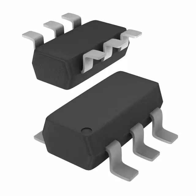
Dual PNP transistor array in a 6-pin SOT-457
The ROHM Semiconductor IMT1AT110 integrates two matched PNP transistors in a single SC-74 (SOT-457) surface-mount package, designated SMT6 as the supplier device package. The 140 MHz transition frequency and a minimum DC current gain (hFE) of 120 at 1 mA, 6 V make it suitable for general-purpose switching and amplification in space-constrained designs.
The 50 V Vce(max) and 150 mA Ic(max) define the safe operating area for each transistor. For a 24 V industrial rail, the 50 V breakdown provides margin for inductive kickback or transient spikes. The 150 mA continuous rating covers typical loads like relay coils, small solenoids, LED indicators, or logic-level signal conditioning. The 300 mW total power budget is shared across both die — if one transistor dissipates 200 mW, the other is limited to 100 mW, so thermal balance matters in continuous operation.
140 MHz transition frequency — switching speed
The 140 MHz ft means the transistor maintains useful gain well into the VHF range. For switching applications, this translates to rise and fall times in the low-nanosecond region at moderate collector currents. It is fast enough for PWM frequencies up to several megahertz, but not intended for RF power amplification. The saturation voltage is specified at 500 mV maximum at 5 mA base current and 50 mA collector current — a typical on-state loss for a small-signal PNP.
150°C junction temperature — industrial and automotive environments
Rated for a maximum junction temperature of 150°C, the IMT1AT110 can operate in environments where ambient temperatures exceed 85°C — such as inside a motor drive enclosure, near an engine bay, or in a power supply with limited airflow. The 300 mW power dissipation must be derated above 25°C using the package's thermal resistance; the small SOT-457 footprint means the PCB copper area acts as the primary heatsink.
Package and footprint — SC-74 / SOT-457
The IMT1AT110 is supplied in the SC-74 (also designated SOT-457) package, a 6-pin surface-mount outline with a 1.5 mm body width and 0.95 mm pin pitch.