Dual-mode topology for unstable supply rails
The BD8P250MUF-CE2 combines buck and buck-boost topologies in one IC, which means it can regulate a fixed 5V output whether the input rail is above 5V (buck mode) or below 5V (boost mode). That is the difference between a part that works on a 12V truck battery and one that still holds 5V when that battery sags to 3.5V during a cold crank. Input range spans 2.7V to 36V, so it tolerates 12V and 24V industrial rails, load-dump transients, and the deep dips you get on automotive buses during engine start. No external clamp needed for 36V peaks.
2A output and thermal reality in a 4x4 mm QFN
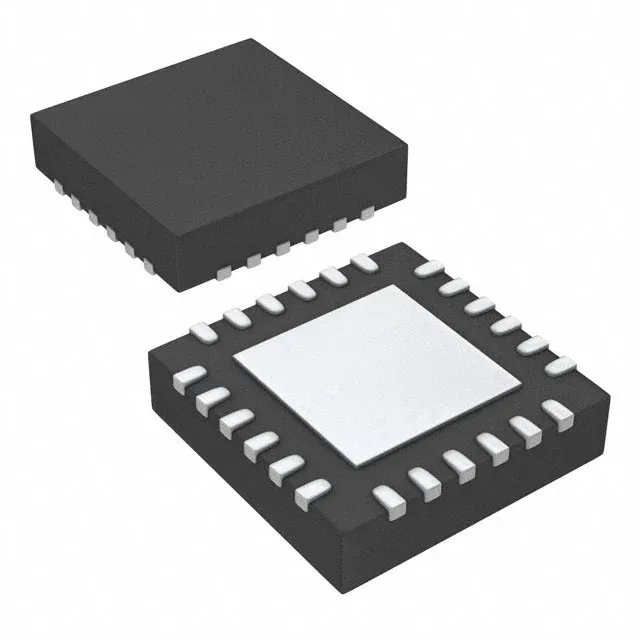
Rated 2A continuous output with synchronous rectification — the internal low-side FET replaces the external Schottky diode, which cuts board space and keeps efficiency above 90% in the 1-2A range. At 2A and 12V in to 5V out, the part dissipates roughly 1.5W; the exposed pad needs a solid thermal via pattern to the ground plane, or the junction hits 125°C before the output reaches full load. Switching at 2.2 MHz lets you use a 2.2-4.7 µH inductor — small enough for a compact layout. The trade-off is that the high edge rate demands tight input-loop routing; a 10 µF ceramic cap within 2 mm of the VIN pin is the difference between a clean rail and radiated noise.
Available in tape-and-reel (TR) or cut-tape (CT). Cut-tape works for prototyping and small runs; TR is the standard for pick-and-place volume. No minimum order quantity beyond the reel increment.