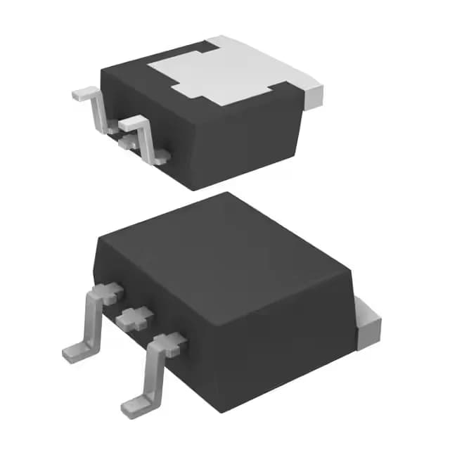
600 V, 45 A N-channel IGBT in LDPAK
The Renesas RJP60D0DPE-00#J3 is a 600 V, 45 A N-channel IGBT in a surface-mount LDPAK (SC-83) package, rated for 122 W maximum power dissipation at a 150°C junction temperature. This is a standard-input-threshold device — the gate drive threshold is compatible with conventional 15 V gate-drive circuits, not the lower-threshold logic-level IGBTs used in some battery-powered designs.
Switching speed and gate drive budget
Total gate charge is 45 nC, measured under the test condition of 300 V rail, 22 A load, 5 Ohm external gate resistor, and 15 V gate drive. At a 20 kHz switching frequency, the average gate-drive current required is 0.9 mA — well within the capability of a standard IGBT gate-driver IC. Turn-on delay is 35 ns and turn-off delay is 90 ns at 25°C; the 90 ns turn-off edge is the longer interval and sets the minimum dead-time in a half-bridge leg to avoid shoot-through.
Conduction loss at the test point
On-state collector-emitter voltage Vce(on) is 2.2 V typical at 15 V gate drive and 22 A collector current. At this operating point, conduction loss is 48.4 W — the dominant loss term in low-frequency switching applications such as 50/60 Hz motor drives or welding inverters. For higher-frequency designs, the switching losses from the 90 ns turn-off tail will add significantly to the thermal budget.
Package and thermal interface
The LDPAK (SC-83) is a large-gauge surface-mount package with a metal collector tab for heat extraction. The PCB footprint must include a copper island beneath the tab — the junction-to-ambient thermal resistance depends heavily on the copper area. This is not a through-hole TO-247 or TO-220; the SMD format suits automated assembly but requires careful thermal vias and a bottom-side heatsink for continuous operation above a few tens of watts.
Lifecycle and sourcing posture
The active status means no last-time-buy risk for new designs, though the LDPAK package limits direct drop-in alternatives from other manufacturers without a PCB layout change.