85V standoff — what the clamping ceiling means for the design
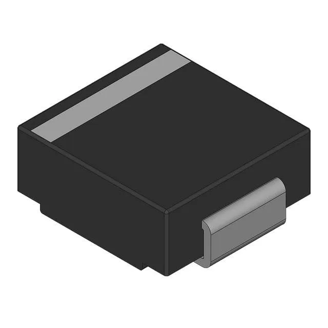
The 1.5SMCJ85A_R1_00001: The reverse standoff of 85V defines the working rail the TVS watches without conducting — the part sits idle above it and clamps below. At the 10.4A peak pulse rating (10/1000 µs waveform), the clamping ceiling is 137V, which is the voltage the downstream circuit sees during a transient event. A 137V clamp on a nominally 85V rail gives roughly 1.6× headroom — adequate for secondary protection on power rails that see inductive kick or ESD injection, but the designer needs to confirm the downstream IC abs-max rating tolerates 137V for the duration of the event.
1.5kW peak pulse rating and the 10/1000 µs condition
Faster transients (8/20 µs) will stress the device differently, so if the application carries IEC 61000-4-2 or similar surge tests, the 1.5kW figure alone is not sufficient — the clamping voltage at the actual test current must be pulled from the V-I curve, not extrapolated from the peak-power rating.
Junction temperature and the 150°C ceiling
The maximum junction temperature is 150°C with an operating range starting at -55°C — this covers the full industrial and outdoor envelope including unmanned enclosures that can seesaw in ambient. Surface-mount SMC (DO-214AB) is the standard tape-and-reel footprint for this power class — compatible with standard pick-and-place tooling and reflow profiles.
General-purpose designation and what it means for second-source
The 1.5SMCJ series is one of the most widely cloned TVS families in the industry — multiple manufacturers offer pin-compatible 1.5kW SMC parts at the same 85V standoff. This means the BOM line has sourcing options beyond the Panjit brand, but the clamping characteristics at the specific transient current should be verified against the alternative datasheet — standoff voltage is not enough; the V-I curve at Ipp is what differentiates two nominally identical parts under stress.