What the 64V standoff and 103V clamping mean for the board
The 1.5SMCJ64A_R1_00001: The reverse standoff of 64 V defines the working voltage the protected rail sits at during normal operation — the TVS stays off and draws only leakage current until a surge pushes it into breakdown. The gap between 64 V and 103 V is the overvoltage let-through window — whatever sits behind this diode sees no more than 103 V during a rated event, which is what protects downstream circuitry that cannot tolerate 150 V or 200 V transients.
DO-214AB package and the 150°C junction ceiling
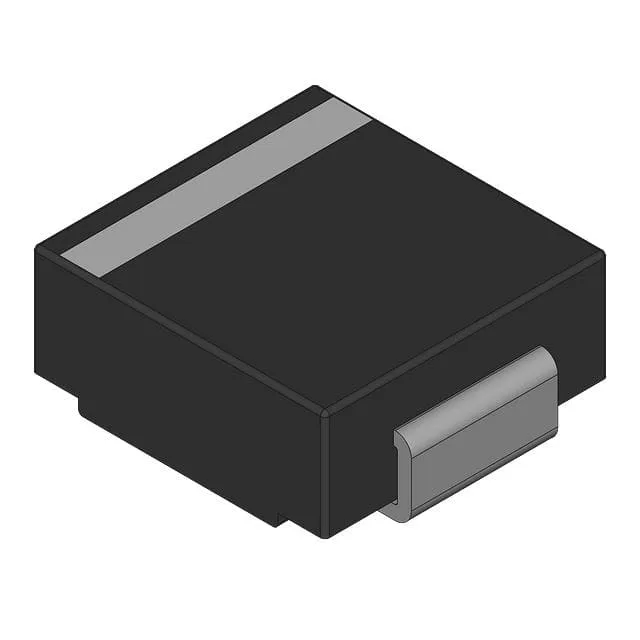
The DO-214AB (SMC) is a non-isolated chip-style package with a thermal pad on the bottom side — it requires a full copper pad under the device for heat spreading, typically the size of the pad land pattern in the recommended footprint. The maximum junction temperature of 150 °C, combined with the 1.5 kW peak pulse rating, means the transient thermal impedance curve (not listed in this spec block but available in the Panjit datasheet) governs the peak-case Tj rise during a single 10/1000 µs event — layout matters because the diode's thermal recovery between transients sets the usable duty cycle in a repetitive-surge environment.
General-purpose unidirectional TVS — what "not power line protection" means
The spec marks Power Line Protection as No — this device is classified for secondary protection on signal lines, control rails, and local bypass nodes rather than as a dedicated AC mains crowbar element. For 230 V AC line-side applications the 103 V clamping ceiling is far below the peak line voltage, and the 1.5 kW rating is insufficient for the high-energy surge environment that IEC 61000-4-5 specifies at the service entry point. Choosing this part for a mains-line role would expose it to energy beyond its rated capability; the correct power-line TVS class carries a higher peak pulse rating and a standoff voltage that matches the AC peak.