Transient protection fit — what the standoff and clamping ratings decide
The 1.5SMCJ54AS_R1_00001: The reverse standoff of 54 V typ sets the bias voltage below which the TVS presents a high-impedance off-state — the protected rail runs at or below this level during normal operation. The breakdown minimum of 60 V gives a 6 V guard band over the standoff, so the part does not turn on below 54 V line noise. When a surge arrives, the clamping maximum of 87.1 V at a 17.2 A peak pulse current is the clamping voltage the downstream circuit sees at that current level. Matching the 10/1000 µs waveform of the spec to your system's surge test class (IEC 61000-4-5, for example) is the primary sizing step; a part rated at a different pulse width absorbs a different energy dose even at the same peak power number. The unidirectional polarity means it protects a single polarity rail — positive transients on the line to ground. For a bidirectional bus or a signal line that swings both ways, a dual-polarity or bidirectional TVS would be needed. The data does not list a bidirectional variant in this family, so confirm the polarity match to your protected node before committing it to the BOM.
DO-214AB SMC package and thermal layout
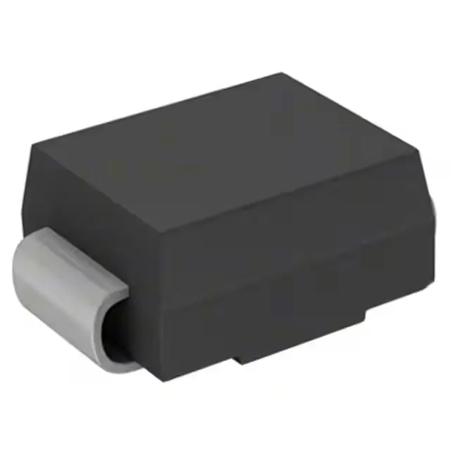
The SMC (DO-214AB) package is the mid-size SMC footprint — larger than the SMA (DO-214AC) and smaller than the SMB (DO-214BA). The land pattern must follow the IPC-7351B generic surface-mount land pattern for the SMC; thermal relief from the cathode tab to the PCB pad directly controls the transient thermal resistance during clamping events. The junction temperature rating of -55°C to 150°C is the maximum allowable internal temperature during the pulse — the device derates from 100% rated peak pulse capability at 25°C ambient toward the 150°C absolute maximum as ambient temperature rises. A thermal pad with adequate copper area on both board surfaces is required to stay within the peak junction temperature at the rated 17.2 A pulse current. Surface-mount pick-and-place assembly is straightforward; the package ships in Tape & Reel (TR) for automated placement and Cut Tape (CT) for low-volume or prototype runs.
Sourcing and production status
The part is listed Active by Panjit International Inc..