Clamping voltage — what 87.1 V means for the downstream load
The 1.5SMCJ54A-AU_R1_000A1: At 87.1 V maximum clamping voltage with a 17.2 A peak pulse (10/1000 µs surge waveform), the TVS diverts surge energy away from whatever circuit sits behind it — the lower the clamping voltage relative to the downstream IC abs-max, the more headroom survives the event. For a 48 V automotive rail this part clamps at 87.1 V, giving roughly 39 V of margin above the standoff rail before the diode turns on.
AEC-Q101 — the automotive qualification that matters for under-hood designs
The AEC-Q101 qualification puts this part through temperature cycling, humidity bias, and surge life testing that a commercial TVS skips — an engine-bay ECU that sees -40 °C at cold crank and 150 °C at the junction under full load needs exactly that margin.
Standoff voltage — the selection axis that sets the rail ceiling
54 V typical reverse standoff is the maximum reverse bias the diode tolerates continuously without conducting — the circuit rail must stay at or below 54 V during normal operation for this part to be the right fit. Any transient that exceeds 54 V triggers the clamping action, pulling the overvoltage down to the 87.1 V ceiling while the diode handles the 17.2 A surge current. 60 V minimum breakdown voltage is the point at which the Zener conduction mechanism formally begins; in practice the clamping knee is softer and the 87.1 V maximum clamping spec is what the downstream circuit must survive.
SMC package and independent sourcing
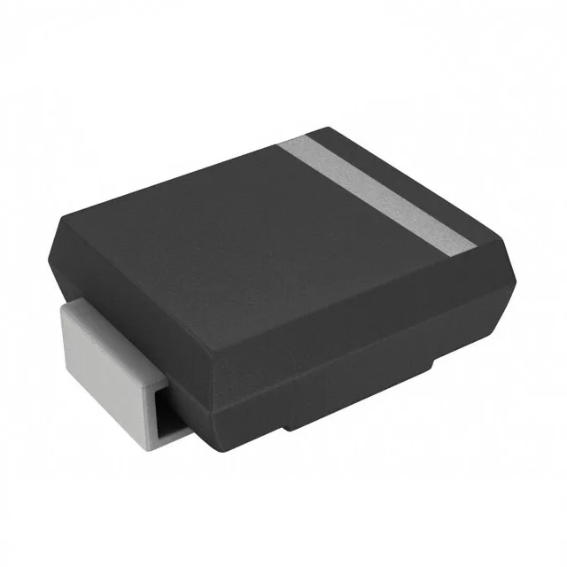
The DO-214AB SMC is the standard large-current TVS footprint — the cathode pad under the package carries the thermal path to the board copper. Both Tape & Reel and Cut Tape packaging are listed, covering high-volume placement and low-volume rework alike.