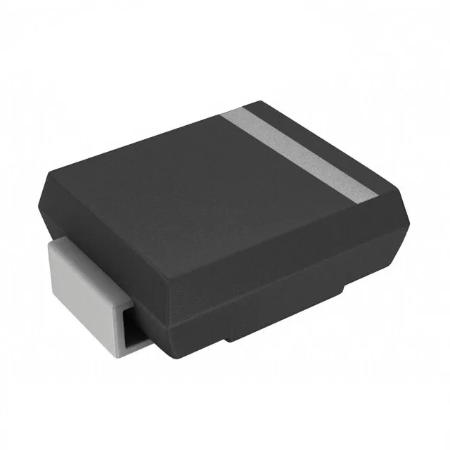
Clamping ceiling — what the 40 V standoff and 1.5 kW peak mean for the board
The 1.5SMCJ40A-AU_R1_000A1: The 40 V reverse standoff defines the working rail the TVS watches in normal operation — it sits unbiased on the line and clips transients above that threshold. When a surge fires, the 23.2 A peak pulse (10/1000 µs waveform) flows and the clamping voltage ceiling is 64.5 V at that current. That standoff/clamp pair is the governing spec for choosing this part against a known transient magnitude and source impedance on the board. 1.5 kW peak pulse is the 10/1000 µs rating — this is the industry's standard surge-waveshape reference for board-level protection upstream of ECU inputs. The part survives a single-event transient of that energy without degradation to the Zener junction. Switching to a faster 8/20 µs surge or repeating the event without adequate inter-event cooling will push the junction toward its 150 °C TJ limit faster than the datasheet thermal budget assumes.
AEC-Q101 — what automotive grade means for the ECU environment
The AEC-Q101 qualification is the discrete-semiconductor counterpart to AEC-Q100 for ICs — it screens the part for temperature cycling, humidity bias, and surge stress that an untested commercial TVS would not survive in an engine-compartment or chassis-domain ECU.
SMC (DO-214AB) — reel, bake, and reflow considerations for EMS
The DO-214AB (SMC) is the mid-range automotive TVS package — wider than the SMB and heavier than the SMA, which means the land pattern and paste mask for the cathode tab carry more solder volume. For a Zener TVS the thermal pad is the anode-side epoxy body, not an exposed paddle, so the primary heat path is through the lead frame to the PCB pad. Confirm the anode/cathode polarity marking on the reel orientation before the pick-and-place program loads — the Cathode band is on the sleeve, not the body, and a reversed part protects the wrong polarity.