What the 1.5 kW clamping rating means
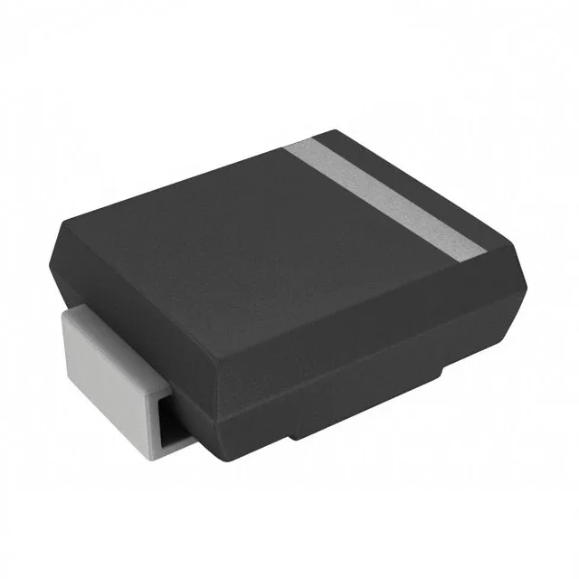
The 1.5SMCJ26A-AU_R1_000A1: At 35.6 A peak pulse current the device clamps at a maximum of 42.1 V, while the reverse standoff sits at a typical 26 V, giving roughly a 1.6× ratio between standoff and the clamping ceiling. For a 24 V automotive rail that sees load dumps and inductive kickback, this standoff headroom accommodates the normal operating voltage while the clamping floor stays below the withstand rating of the downstream IC. The distinction between the Zener type designation and a true TVS is largely naming convention in this power class — both achieve the same avalanche clamping mechanism and the same 1.5 kW peak rating. Because power-line protection is listed as No, this part is intended for signal-line or localized node protection rather than an entire 12/24 V distribution bus rated for load-dump survival at the supply entry point. The SMC (DO-214AB) package is a standard pick-and-place surface-mount body; the cathode bar on the sleeve identifies polarity before the silk legend. Tape-and-reel and cut-tape packaging serve both high-volume assembly runs and low-quantity prototyping alike. For a board being designed into an ECU or BCM, the selection parameter that drives the BOM decision is the clamping voltage at the peak pulse current the board is expected to see in its environment — not the headline 1.5 kW figure alone. A 35.6 A pulse rating means the part survives the event and returns to blocking without degradation, as long as the energy in the transient stays within the 1.5 kW × pulse-duration product. The minimum breakdown of 28.9 V sets the point where conduction begins — the standoff at 26 V keeps the diode in its high-impedance state during normal operation so no leakage current loads the protected node continuously.