Clamping performance — what 356V and 4.2A mean for the protected rail
The 1.5SMCJ220AS_R1_00001: The 220V standoff voltage is the maximum working voltage the protected rail can sit at continuously without the TVS conducting — this part sits across a nominal line that must stay below that threshold in normal operation. At 1.5 kW peak pulse, the 356V clamping ceiling is the voltage present at the protected node during the event — downstream silicon sees that spike width, not the raw transient. Selecting a standoff with adequate headroom above the nominal rail (for example a 24 V rail uses a standoff in the 27–33 V range; this part targets 220 V nominal rails) is the primary sizing decision for any TVS in a protection chain.
Package and thermal integration
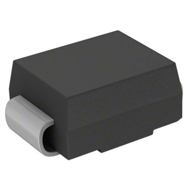
The DO-214AB (SMC) package is the standard foot-print for 1.5–3 kW TVS diodes across multiple manufacturers — the cathode bar in the centre divides the package lengthwise and carries the thermal path to the board pad. Junction temperature is calculated from ambient plus the Ipp × Vc product multiplied by the board-level thermal resistance; the board pad under the cathode bar is the primary heatsinking path for a surface-mount TVS, so the footprint pad should not be undersized even in a space-constrained layout.
Sourcing posture and lifecycle
Panjit lists the part as Active — it is a current-production line item available through independent distribution. Confirm the datasheet clamping curve and peak pulse waveform before substituting — 10/1000 µs is the defining surge shape for this power class. Quoted to order; availability and lot traceability confirmed at RFQ.