TVS clamping ratings for a 200V rail
The 1.5SMCJ210CA_R1_00001 holds off at 210V nominal — meaning the protected rail sits below the breakdown threshold during normal operation, and the device presents a high impedance to the line. That 340V ceiling is the clamping voltage the downstream circuitry must withstand — it determines whether this part clears the protection gap on a 200V-rated signal or control line. Peak pulse power is rated at 1500 W (1.5 kW) for the 10/1000 µs wave shape defined in the TVS standard — the 4.4 A figure follows directly from dividing 1500 W by the 340 V clamping level. If the transient duration or peak current exceeds that profile, the clamping voltage rises above 340 V and the part may not recover; sizing the TVS requires confirming the worst-case transient energy stays within the 1.5 kW rating.
DO-214AB SMC in the protection chain
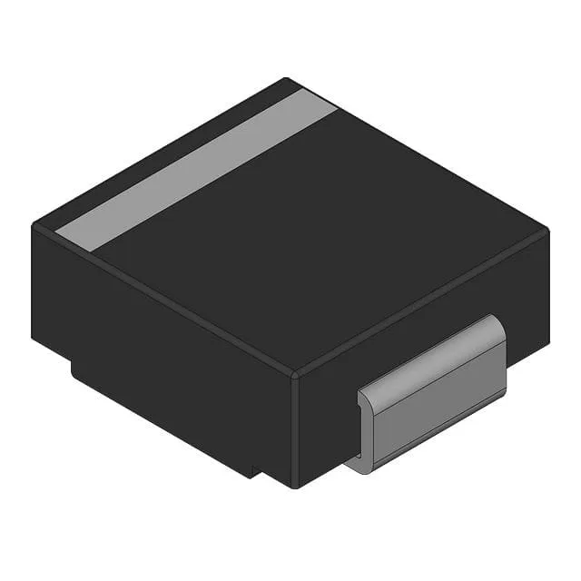
The DO-214AB (SMC) package is the standard outline for 1.5–3 kW TVS diodes — the copper clip inside the package carries the peak pulse current during a clamp event, and the lead frame tab solders directly to the PCB pad for thermal relief. Surface-mount pick-and-place compatible, it ships on tape-and-reel or cut tape for automated assembly. The ledger flags power line protection as No — the 1.5SMCJ series is intended for secondary protection on signal, control, and low-current distribution rails rather than directly across the AC mains. Primary power-line protection typically calls for higher-energy parts rated for higher peak currents and repetitively applied transients.
Active sourcing posture
Confirm the BOM position count and the exact polarity orientation before committing — the CA suffix designates the bidirectional polarity in this series, and orientation on a unidirectional rail protection scheme must be verified against the board schematic.