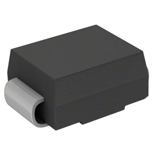
What a 1.5 kW TVS diode actually does
The 1.5SMCJ190AS_R1_00001 is a unidirectional TVS (transient voltage suppressor) in the SMC (DO-214AB) package — it clamps voltage spikes on a line before they reach downstream circuitry, then self-resets once the event passes. The 1.5 kW peak pulse power rating defines the energy-handling ceiling — a 1 µs ring wave or 10/1000 µs surge absorbed once per the spec window stays within it.
Clamping voltage and standoff — the two numbers that decide fit
Standoff voltage (190 V typ) is what the line normally runs at — design the PCB trace, cable, and input capacitance around 190 V as the working rail. Breakdown minimum (209 V) is the threshold where the TVS begins conducting; it sits 10 % above standoff, which is the standard surge-withstand margin for this class. Clamping maximum (308 V) is what the downstream IC or load sees when the TVS is fully engaged at 4.8 A — that 118 V differential (308 V minus 190 V) across the series impedance of the protection path is the stress the protected circuit must tolerate at the event peak. The 1.5SMCJ190AS_R1_00001 is listed as not suitable for power-line protection, so it is not the right part for 220/230 V AC mains clamping — it is sized for DC rail, signal line, or low-energy transient protection at working voltages up to roughly 190 V DC.
SMC package and board integration
The DO-214AB (SMC) footprint mounts surface mount and mates with a standard SMA-adjacent land pattern — the cathode band marks the unidirectional polarity on the reel orientation. Solder joint inspection and the thermal pad delta between pins matters more than on a through-hole part; a hot-air rework profile at 260 °C peak with a 3 °C/s ramp is typical for this package, but the junction temperature limit of 150 °C constrains the dwell time above the reflow window. Packaged on Tape & Reel (TR) with Cut Tape (CT) option — the reel count matters for high-volume SMT line setup; confirm the pick-and-place nozzle diameter suits the SMC body width of 7.98 mm x 6.22 mm.