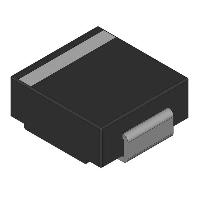
The 1.5SMCJ16CA_R1_00001: The 1500 W peak pulse rating (10/1000 µs waveform) tells you how much transient energy the diode absorbs without failing — this is the number that decides whether the TVS fits behind a supply rail that sees inductive kickback or lightning-surge injection on the input side. For a 16 V rail, the 17.8 V minimum breakdown and the 26 V clamping ceiling mean the downstream circuitry sees no more than 26 V during the event, clamped at 57.7 A peak.
Clamping ceiling — the actual number protecting your node
The 26 V clamping voltage at peak pulse current is what your downstream IC actually sees during the event. Bidirectional single-channel construction means it clamps both polarities — useful on floating rails, transformer-coupled lines, or anywhere the fault can reverse-bias the protected node. Unidirectional TVS diodes leave one polarity unprotected; this part does not have that gap.
DO-214AB SMC — reworkability and board footprint
The DO-214AB (SMC) package is one of the more rework-friendly large-chip packages. The cathode bar is the wide pad on the top surface — thermal resistance from junction to ambient is set by the solder pad area on the board, not the package itself. Pre-heating the board to 150 °C before hot-air application prevents pad lift on this footprint. The SMC is wider than a SMB or SMA package, so check your pad spacing before dropping it into an SMA-designated layout.