What the clamping ratings mean for your protection design
The 1.5SMCJ110A_R1_00001: The reverse standoff of 110 V typ sets the working voltage the TVS can hold off indefinitely without conduction — the circuit runs below this rail under normal operation. Breakdown kicks in at 122 V minimum, which means the device guarantees it is OFF below that threshold. That 67 V differential between standoff and clamping ceiling is the voltage margin the downstream IC sees before the TVS turns hard on — it is the defining spec for how much stress survives the clamp. This is not a continuous dissipation rating — it is a single-event, short-duration capability. Board-level layout matters here: the SMC package thermal path runs through the cathode pad to the board copper, so a modest landing pad and thin dielectric under the part will push junction temperature above the 150 °C ceiling on repeated events.
The 150 °C maximum junction rating is well above the 125 °C many consumer-grade TVS parts cap out at. This headroom matters in sealed enclosures, multi-board stacks where adjacent components dump heat onto the plane, or outdoor equipment where solar load adds to the thermal budget. At the cold end, -55 °C qualification covers cold-start transients and outdoor winter deployments without derating concerns — the clamping voltage actually tightens at low temperature, so the protection level improves, not degrades.
SMC package and surface-mount assembly context
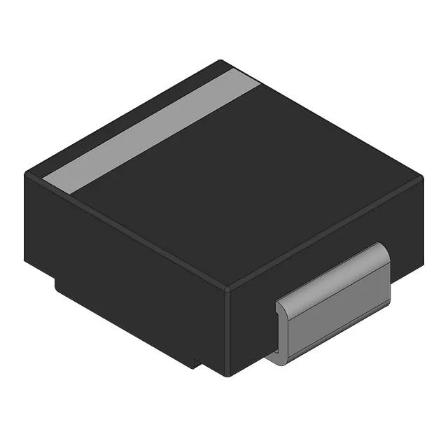
The DO-214AB (SMC) is a dominant package for 1500 W TVS parts — the cathode bar and wide body give the thermal pad area needed for single-pulse energy absorption. Tape-and-reel packaging (TR) is standard; cut tape (CT) is also listed, which suits prototype quantities without committing to a full reel. Surface-mount reflow profile follows the standard lead-free schedule — no special thermal excursion is required compared to other SMC parts.