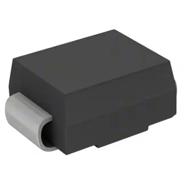
The 1.5SMC8.2CA_R1_00001: In a 24 V input rail protected against IEC 61000-4-5 surge, a 1.5 kW rated part at 7.02 V standoff will clip the spike at 12.1 V maximum and let the clamping action absorb the current — the downstream load sees a clamped 12.1 V instead of the raw surge voltage.
The three-voltage window: standoff, breakdown, clamping
The minimum breakdown of 7.79 V is where the Zener mechanism kicks in, and the clamping voltage of 12.1 V is where the peak pulse current of 124 A is clipped. In practice the clamping voltage is what your downstream IC or motor driver sees — 12.1 V at 124 A gives you a defined protection ceiling. Because the CA suffix marks a bidirectional device, the 7.02 V standoff and 12.1 V clamping window applies in both polarities — useful for protecting AC signal lines or differential pairs where the transient can swing either direction.
150 °C junction limit and thermal margin
A 150 °C maximum junction leaves real margin against self-heating during a clamping event — the transient is brief (10/1000 µs) so thermal duty cycle matters more than absolute peak. Repeated transients without sufficient cooling interval will push the junction toward that 150 °C ceiling; thermal design of the board copper around the SMC land pattern governs the repetition rating.
DO-214AB SMC — footprint, assembly, and rework
The DO-214AB (SMC) package is the standard industry footprint for 1.5–3 kW TVS diodes — the wide cathode pad on the bottom gives good heat spreading to the board copper. Surface-mount reflow profile is standard SAC305; the part tolerates the usual peak temperature reflow. The package orientation is polarity-critical — the cathode band marks the polarity direction on the body, which matters for correct bidirectional clamping behaviour.