What the standoff and clamping ratings mean for your protection circuit
The 1.5SMC75A_R1_00001 holds off at 64.1 V typical — the circuit runs clean below that without the TVS conducting. That 103 V ceiling is what your downstream ICs must survive — the tighter the clamp, the less margin your protected circuitry needs. Rated 1500 W peak pulse — that is the 1.5 kW the series name carries, measured on the 10/1000 µs surge curve.
Temperature range and the unidirectional Zener mechanism
The upper limit is specified as TJ (junction), not ambient — the board thermal design determines whether the part actually runs near that ceiling. One unidirectional channel means it handles one polarity only. For a 75 V nominal rail this is standard — positive transients are clamped, negative excursions are forward-biased through the Zener knee. If the line needs bipolar protection a second opposite-polarity TVS is added.
DO-214AB SMC footprint and reel packaging
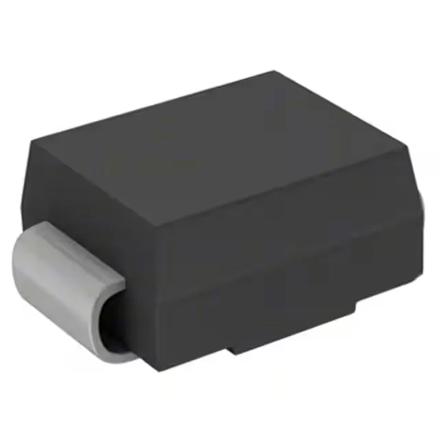
DO-214AB (SMC) is the standard 1.5 kW TVS land pattern — wide adoption means the footprint is compatible across manufacturers. The part ships on Tape & Reel or Cut Tape, which covers both production run and prototype quantities without minimum order quantity friction. Surface-mount termination — no through-hole mounting. The SMC flat-body profile sits flush on the pad; reflow profile must stay below the junction temperature limit, so a thermocouple at the case during profiling is the standard qualification step for the first board spin.
Active status and sourcing posture
The 1.5SMC series covers 10 V through 440 V standoff in the same SMC package, so second-source options at 75 V exist from multiple manufacturers in the same footprint.