What the voltage ratings mean for the protected rail
The 1.5SMC6.8A_R1_00001: The reverse standoff of 5.8V sets the working voltage below which the diode is off and draws only leakage — the rail runs undisturbed in normal operation. Breakdown kicks in at 6.45V minimum, and at the peak pulse current the clamping ceiling is 10.5V. In practice that 10.5V is what the downstream circuit sees during a transient; the protected node must tolerate that clamping level without damage. The 143A peak pulse rating (10/1000 µs) confirms the diode survives the surge current the clamping voltage is measured at — a lower-rated part would clamp higher under the same event.
1.5 kW and the TJ ceiling — why the temperature grade matters
What actually limits the lifetime is the junction temperature swing. Layout under the SMC package must leave enough copper pour to keep RthJC low enough that self-heating stays below that 150°C ceiling during repeated transients.
SMC package and tape packaging for SMT assembly
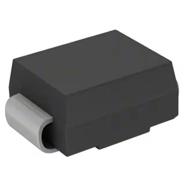
The DO-214AB (SMC) is a standard 2-pin SMA-size outline — almost every pick-place feeder handles it and the footprint matches the common TVS landing pattern. The cathode band is the single stripe; orientation is unambiguous on reflow. Available in Tape & Reel for high-volume SMT lines and Cut Tape for low-run or prototype builds — the cut-tape orientation on the reel carrier matters for reel-based handlers, so confirm the supplier wound it with the cathode band in the correct direction before loading the feeder.